|
Electric Wiring and Repairs |
|
|
220 Volt Furnace Neutral Wire220v electric furnace hook up. for a furnace. I have installed a 220v electric furnace but have not finished the wire hook up and need some help.2 Wire and 3 Wire CablesHow do you know when to use 12-2 versus 12-3, 14-3 versus 14-2. I keep on getting confused on when to use 2 wire versus 3 wire.30 Amp Disconnect WiringI'm putting in a 30amp disconnect with 10/3 AWG with a ground wiring. The disconnect is a signal phase with ground no neutral bar.3 Phase Wiring For An Air ConditionerOn a 3 phase wire system, does it matter what the orientation of the BLACK, RED and BLUE is when hooking up an industrial AC unit?Attic Wiring For A Security LightI would like to add an additional security light in a gable end of my home. The attic space is not used and is full of blown insulation.Baileigh Shear Electrical WiringI bought a shear for my garage that is rated for 220 volt single phase and I'm a little confused with the wiring diagram.Bedroom WiringI am changing out my home fuse box to a circuit box Additional Info I am doing a master bedroom remodel.Building WiringI greatly appreciate your effort in training electricians to be able to work on electrical projects at most every home.Electrical Codes For Basement WiringWhen installing electrical circuit wiring in a basement that will be wired through the ceiling to a first floor outlet near the floor of that level, is Romex wire OK? We have heard that you should use metal cable.Garage Wiring ProjectI have been attempting to rewire parts of my garage, so I could have drywall hung. The box in the picture contains 4 wires.Jandy Aqua Link Controller WiringI have a Jandy Aqua link RS4 that run my computer equipment daily. Our dog bit into the wire that runs from the pool computer box outside to the control panel inside my home.Loose Wiring ConnectionsI have replaced a good amount of receptacles in my home, and I'm the type of person that worries about every last thing possible and mainly about burning my house down.Oven Electrical WiringI'm installing an oven. Behind the electrical wall plate i have a ground wire, black and white but on my oven i have a red, black, green, and a white.Questionable Electrical WiringI had hired a electrician to run under cabinet lighting in my kitchen however for another problem not relating to that i had another electrical contractor through the house today and the holes are not patched from your install and he stated some alarming potential hazards with the install that i wanted to clear up.Wire Size For 1200 WattsWhat GAGE wire or wire size is appropriate to handle up to 1200 watts of home current on a 120 volt, 20 amp circuit.Wire Size For A Pond PumpI am running an electric circuit from my electrical power box about 800 feet for a pump at my pond.Wire StrippingElectrical Wiring Question I noticed a few web sites warned about not getting nicks in the wires as your stripping them.Wire Stripping GuidelinesSome of the 14 gauge wires I stripped to attach to receptacles will sometimes how a ring near the base of the wire after it is stripped, and I use a good quality craftsman wire stripper, making sure that I use the 14 gauge notch.Wiring A ThermostatReplacing Honeywell t6160 room stat (Mains, 3-wire)with Horstmann DRT2 (Battery operated, 2-wire).Wiring Bathroom Exhaust Fan and LightI want to wire a bathroom exhaust fan to come on when the light over the shower is on to exhaust moisture, but also want to be able to operate the fan independently on another switch without the shower light on to exhaust odor.Wiring Ceiling Fans With Remote ControlAll the existing ceiling fans in my house are wired to 2 switches, one for the fan and one for the light.Wiring Diagram SoftwareThis is my first visit to your site. Can you recommend any electrical wiring software?.Wiring GarageA few years back I installed a sub panel in my garage to run my 220 Volt Welder and air compressor.Wiring Porcelain Lamp HolderI purchased a Leviton Porcelain Lamp holder with a pull chain, the rating is 660W 250V at Home Depot. |
|
|
Electrical Question from Rowell about Electrical Wiring Dave’s Reply: The Following links will assist you with your electrical question: For more information about Electrical Wiring This link is helpful as a Contractor Make sure not to miss these Resources for: Wiring Diagrams Be Careful and Be Safe – Never Work on Energized Circuits! For Best Results Consult a Licensed Electrical Contractor. Electrical Question from Rowell about Electrical Wiring Dave’s Reply: The Following links will assist you with your electrical question: For more information about Electrical Wiring This link is helpful as a Contractor Make sure not to miss these Resources for: Wiring Diagrams Be Careful and Be Safe – Never Work on Energized Circuits! For Best Results Consult a Licensed Electrical Contractor. Wiring a 3 Prong Dryer Cord
Background: Toni, from Santa Cruz, California. Additional Comments: Your website was helpful in showing me how to switch out a 3 prong to a 4 prong dryer cord. Dave’s Reply: Connecting 3Wire and 4Wire Dryer CordsApplication: How to Wire a 3Prong Cord for an Electric Dryer, How to wire a 4 prong dryer plug. How to Hook Up a 3Wire and 4Wire Dryer Cord
See More about Wiring a Dryer CordThe following resources will help you with the electrical wiring connections for your dryer. How to Wire a 3-Prong and 4-Prong Dryer Cord Dryer Cord Electrical Wiring
Wiring a 3 Prong Dryer Cord
Background: Toni, from Santa Cruz, California. Additional Comments: Your website was helpful in showing me how to switch out a 3 prong to a 4 prong dryer cord. Dave’s Reply: Connecting 3Wire and 4Wire Dryer CordsApplication: How to Wire a 3Prong Cord for an Electric Dryer, How to wire a 4 prong dryer plug. How to Hook Up a 3Wire and 4Wire Dryer Cord
See More about Wiring a Dryer CordThe following resources will help you with the electrical wiring connections for your dryer. How to Wire a 3-Prong and 4-Prong Dryer Cord Dryer Cord Electrical Wiring
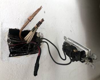
Wiring a Smart Light Switch Electrical Question: I am trying to connect a smart light switch. The existing switch only has two black wires connected to it, which I assume are the line and load wire. How to Wire Light Switch
Thank you! This electrical wiring question came from Jeff in Honolulu, Hawaii. Dave’s Reply: Thanks for your electrical wiring question Jeff. How to Wire a Smart Light SwitchApplication: How to Wire a Smart Light Switch. Wire a TP-Link Smart Light Switch in a GarageThis electrical wiring project is about wiring a smart light switch in the garage of a old house. Light Switch How to Wire
More about How to Wire a Light SwitchWiring a Light Switch – Diagram 1Wiring Diagrams Electrical Wire for the HomeComplete listing of electrical wire types and parts used for home projects with electrical code information serves as selection guidelines. Sub-Panel Electrical Wiring for the HomeElectrical sub-panel wiring considerations for the home complete with pictures. Careful planning for your Sub-Panel with immediate and future load considerations will help you understand how to size your Sub-Panel. This information will help as you consider a Sub-Panel and its size. Electrical Boxes for Electric Repairs and Home Wiring Projects Electrical Junction Boxes for Home WiringUnderstanding electrical junction boxes and what they are used for. Home electrical wiring is the process of installing electrical wire to a location that will serve electrical devices or an appliance. One very important component is the box where the wire will be installed. The type and size of the home wiring electrical boxes will depend upon the circuit size, application and its location. How to Install Garage Electrical Wiring Garage Electrical WiringFully Explained Photos and Wiring Diagrams for Garage Electrical Wiring with Code Requirements for most new or remodel projects. Electrical Grounding and Ground Wires Electrical Grounding Methods and RequirementsListing of electrical codes for grounding with examples of electrical grounding codes for home electrical wiring. Wiring a Smart Light Switch Electrical Question: I am trying to connect a smart light switch. The existing switch only has two black wires connected to it, which I assume are the line and load wire. How to Wire Light Switch
Thank you! This electrical wiring question came from Jeff in Honolulu, Hawaii. Dave’s Reply: Thanks for your electrical wiring question Jeff. How to Wire a Smart Light SwitchApplication: How to Wire a Smart Light Switch. Wire a TP-Link Smart Light Switch in a GarageThis electrical wiring project is about wiring a smart light switch in the garage of a old house. Light Switch How to Wire
More about How to Wire a Light SwitchWiring a Light Switch – Diagram 1Wiring Diagrams Electrical Wire for the HomeComplete listing of electrical wire types and parts used for home projects with electrical code information serves as selection guidelines. Sub-Panel Electrical Wiring for the HomeElectrical sub-panel wiring considerations for the home complete with pictures. Careful planning for your Sub-Panel with immediate and future load considerations will help you understand how to size your Sub-Panel. This information will help as you consider a Sub-Panel and its size. Electrical Boxes for Electric Repairs and Home Wiring Projects Electrical Junction Boxes for Home WiringUnderstanding electrical junction boxes and what they are used for. Home electrical wiring is the process of installing electrical wire to a location that will serve electrical devices or an appliance. One very important component is the box where the wire will be installed. The type and size of the home wiring electrical boxes will depend upon the circuit size, application and its location. How to Install Garage Electrical Wiring Garage Electrical WiringFully Explained Photos and Wiring Diagrams for Garage Electrical Wiring with Code Requirements for most new or remodel projects. Electrical Grounding and Ground Wires Electrical Grounding Methods and RequirementsListing of electrical codes for grounding with examples of electrical grounding codes for home electrical wiring. Wiring a Air Compressor with GFCI Protection Wiring a GFCI Circuit for a 240Volt Air Compressor Craig asks: Installing 8o gal air compressor that requires a 30 amp breaker, I have a hot tub hook up that I don’t use anymore with a 50 amp GFCI box located outside and runs to the main breakers box. I have a 30 amp breaker I was planning on using in the main box. My question is can I use the 50 amp GFCI breaker outside as a hook up or does it need to be the same size breaker as inside the main box? Or should I get another breaker that’s not GFCI and use it as a shut off? Wire is 6 gauge also. Dave’s Reply: Thanks for your electrical wiring question Craig. 240Volt Air Compressor with GFCI ProtectionApplication: Change the Wiring from a Hot Tub to a Air Compressor with GFCI Protection. Wiring a Air Compressor in a Back YardThis electrical wiring project is about Changing the Wiring from a Hot Tub GFCI to a GFCI for an Air Compressor in the Back Yard of a Old Home. Air Compressor Disconnect and GFCI Protection
See More about How to Change the Wiring a GFCI OutletElectrical Wire for the HomeComplete listing of electrical wire types and parts used for home projects with electrical code information serves as selection guidelines. Home Electrical Circuit Breakers Home Electrical Circuit BreakersA guide to home electrical circuit breakers and how they work to protect your electrical wiring. When properly installed, your home electrical wiring is protected by a circuit protection device. Wiring Electrical Outlets for the HomeHome electrical wiring includes 110 volt outlets and 220 volt outlets and receptacles which are common place in every home. See how wiring electrical outlets for the home are done. GFCI and GFI Wiring DiagramsThe features and benefits of GFCI outlets and receptacles will give you a clear understanding of the importance why these safety devices are required by code to help protect you and your family against accidental electrical shock hazards. Home Electrical Wiring Projects Home Wiring ProjectsInstalling electrical wiring projects for safety and home improvements. Wiring a Air Compressor with GFCI Protection Wiring a GFCI Circuit for a 240Volt Air Compressor Craig asks: Installing 8o gal air compressor that requires a 30 amp breaker, I have a hot tub hook up that I don’t use anymore with a 50 amp GFCI box located outside and runs to the main breakers box. I have a 30 amp breaker I was planning on using in the main box. My question is can I use the 50 amp GFCI breaker outside as a hook up or does it need to be the same size breaker as inside the main box? Or should I get another breaker that’s not GFCI and use it as a shut off? Wire is 6 gauge also. Dave’s Reply: Thanks for your electrical wiring question Craig. 240Volt Air Compressor with GFCI ProtectionApplication: Change the Wiring from a Hot Tub to a Air Compressor with GFCI Protection. Wiring a Air Compressor in a Back YardThis electrical wiring project is about Changing the Wiring from a Hot Tub GFCI to a GFCI for an Air Compressor in the Back Yard of a Old Home. Air Compressor Disconnect and GFCI Protection
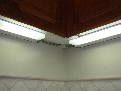
See More about How to Change the Wiring a GFCI OutletElectrical Wire for the HomeComplete listing of electrical wire types and parts used for home projects with electrical code information serves as selection guidelines. Home Electrical Circuit Breakers Home Electrical Circuit BreakersA guide to home electrical circuit breakers and how they work to protect your electrical wiring. When properly installed, your home electrical wiring is protected by a circuit protection device. Wiring Electrical Outlets for the HomeHome electrical wiring includes 110 volt outlets and 220 volt outlets and receptacles which are common place in every home. See how wiring electrical outlets for the home are done. GFCI and GFI Wiring DiagramsThe features and benefits of GFCI outlets and receptacles will give you a clear understanding of the importance why these safety devices are required by code to help protect you and your family against accidental electrical shock hazards. Home Electrical Wiring Projects Home Wiring ProjectsInstalling electrical wiring projects for safety and home improvements. Wiring a Under Cabinet LED Light Electrical Question: I am trying to install new led under cabinet lights, all the wires are are 14 gauge. How to Wire Under Cabinet Light Mike asks: This electrical wiring question came from Mike in Los Angeles, California. Dave’s Reply: Thanks for your electrical wiring question Mike. How to Wire a Under Cabinet LightApplication: How to Wire a Under Cabinet Light. How to Wire a Under Cabinet Light in a KitchenThis electrical wiring project is about How to Wire a Under Cabinet Light in the Kitchen of a Old Home. Under Cabinet Light How to Wire
More about How to Wire a Under Cabinet LightWiring a Light Switch – Diagram 1Wiring Diagrams Electrical Wire for the HomeComplete listing of electrical wire types and parts used for home projects with electrical code information serves as selection guidelines. How to Install Kitchen Electrical Wiring Kitchen Electrical WiringFully Explained Photos and Wiring Diagrams for Kitchen Electrical Wiring with Code Requirements for most new or remodel projects. Lighting for the Home How to Install Cabinet Lighting Installing Under Cabinet LightsInstalling under cabinet lights for your home electrical improvements. This article explains installing under cabinet lights and the lighting features you should know about. Electrical Grounding Methods and RequirementsListing of electrical codes for grounding with examples of electrical grounding codes for home electrical wiring. Wiring a Under Cabinet LED Light Electrical Question: I am trying to install new led under cabinet lights, all the wires are are 14 gauge. How to Wire Under Cabinet Light Mike asks: This electrical wiring question came from Mike in Los Angeles, California. Dave’s Reply: Thanks for your electrical wiring question Mike. How to Wire a Under Cabinet LightApplication: How to Wire a Under Cabinet Light. How to Wire a Under Cabinet Light in a KitchenThis electrical wiring project is about How to Wire a Under Cabinet Light in the Kitchen of a Old Home. Under Cabinet Light How to Wire
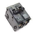
More about How to Wire a Under Cabinet LightWiring a Light Switch – Diagram 1Wiring Diagrams Electrical Wire for the HomeComplete listing of electrical wire types and parts used for home projects with electrical code information serves as selection guidelines. How to Install Kitchen Electrical Wiring Kitchen Electrical WiringFully Explained Photos and Wiring Diagrams for Kitchen Electrical Wiring with Code Requirements for most new or remodel projects. Lighting for the Home How to Install Cabinet Lighting Installing Under Cabinet LightsInstalling under cabinet lights for your home electrical improvements. This article explains installing under cabinet lights and the lighting features you should know about. Electrical Grounding Methods and RequirementsListing of electrical codes for grounding with examples of electrical grounding codes for home electrical wiring. 15amp Circuit Breaker Problem Electrical Question: When I have the lights on and use anything it pops the breaker. Can I change the 15amp to a 20amp breaker? Tripping Breaker Main Panel Charles asks: I have a big garage. The entire garage is on the same 15 amp circuit. When I have the lights on and use anything else it pops the breaker. For example air compressor, 120v welder, or fans (not all at the same time). I was wondering if I can replace the 15 amp for a 20amp breaker. House was built in 2018. This electrical wiring question came from Charles in Surprise, Arizona. Dave’s Reply: Thanks for your electrical wiring question Charles. Tripping 15amp Breaker ProblemApplication: Tripping Breaker a Main Panel. Tripping Breaker a Main Panel in a Attached GarageThis electrical wiring project is about Tripping Breaker a Main Panel in the Attached Garage of a New Home. Overloaded Circuit Causes a 15amp Breaker to Trip Off
See More about Tripping Breaker a Main PanelHome Electrical Codes for Main Service Panels Sub-Panel Electrical Wiring for the HomeElectrical sub-panel wiring considerations for the home complete with pictures. Careful planning for your Sub-Panel with immediate and future load considerations will help you understand how to size your Sub-Panel. This information will help as you consider a Sub-Panel and its size. Home Electrical Circuit Breakers Home Electrical Circuit BreakersA guide to home electrical circuit breakers and how they work to protect your electrical wiring. When properly installed, your home electrical wiring is protected by a circuit protection device. How to Install Garage Electrical Wiring Garage Electrical WiringFully Explained Photos and Wiring Diagrams for Garage Electrical Wiring with Code Requirements for most new or remodel projects. How to Install Workshop Electrical Wiring Work Shop Electrical WiringFully Explained Photos and Wiring Diagrams for Workshop Electrical Wiring with Code Requirements for most new or remodel projects. 15amp Circuit Breaker Problem Electrical Question: When I have the lights on and use anything it pops the breaker. Can I change the 15amp to a 20amp breaker? Tripping Breaker Main Panel Charles asks: I have a big garage. The entire garage is on the same 15 amp circuit. When I have the lights on and use anything else it pops the breaker. For example air compressor, 120v welder, or fans (not all at the same time). I was wondering if I can replace the 15 amp for a 20amp breaker. House was built in 2018. This electrical wiring question came from Charles in Surprise, Arizona. Dave’s Reply: Thanks for your electrical wiring question Charles. Tripping 15amp Breaker ProblemApplication: Tripping Breaker a Main Panel. Tripping Breaker a Main Panel in a Attached GarageThis electrical wiring project is about Tripping Breaker a Main Panel in the Attached Garage of a New Home. Overloaded Circuit Causes a 15amp Breaker to Trip Off
See More about Tripping Breaker a Main PanelHome Electrical Codes for Main Service Panels Sub-Panel Electrical Wiring for the HomeElectrical sub-panel wiring considerations for the home complete with pictures. Careful planning for your Sub-Panel with immediate and future load considerations will help you understand how to size your Sub-Panel. This information will help as you consider a Sub-Panel and its size. Home Electrical Circuit Breakers Home Electrical Circuit BreakersA guide to home electrical circuit breakers and how they work to protect your electrical wiring. When properly installed, your home electrical wiring is protected by a circuit protection device. How to Install Garage Electrical Wiring Garage Electrical WiringFully Explained Photos and Wiring Diagrams for Garage Electrical Wiring with Code Requirements for most new or remodel projects. How to Install Workshop Electrical Wiring Work Shop Electrical WiringFully Explained Photos and Wiring Diagrams for Workshop Electrical Wiring with Code Requirements for most new or remodel projects. Problem With Electrical Circuits During Hot Weather Electrical Question: What is causing a problem with my electrical power in my home? Jay, a Homeowner from San Diego, California asks:
Additional Comments: Great website! Dave’s Reply: Home Electrical Circuit ProblemsApplication: Electric Power Problem. Guide to Troubleshooting Electric Circuit Problems
More about Troubleshooting Home Electrical ProblemsUsing Electrical Testers and Meters Understanding Electrical TestersWhen working on home electrical wiring using voltage testers can play an important part in electrical safety. Electrical testers enable you to identify electrical circuits and help prevent the possibility of accidental electrical shock. How to Troubleshoot and Repair Electrical WiringLicensed Electrician Reveals the Secrets of Successful Electrical Troubleshooting Methods used to solve the majority of the home electrical problems and wiring failures encountered. House Wiring Circuits and Circuit BreakersThis article looks at common 120 volt and 240 volt house wiring circuits and the circuit breakers that are installed identifying the types and amperage sizes used in most homes. Electrical Circuit BreakersA guide to home electrical circuit breakers and how they work to protect your electrical wiring. When properly installed, your home electrical wiring is protected by a circuit protection device. Problem With Electrical Circuits During Hot Weather Electrical Question: What is causing a problem with my electrical power in my home? Jay, a Homeowner from San Diego, California asks:
Additional Comments: Great website! Dave’s Reply: Home Electrical Circuit ProblemsApplication: Electric Power Problem. Guide to Troubleshooting Electric Circuit Problems
More about Troubleshooting Home Electrical ProblemsUsing Electrical Testers and Meters Understanding Electrical TestersWhen working on home electrical wiring using voltage testers can play an important part in electrical safety. Electrical testers enable you to identify electrical circuits and help prevent the possibility of accidental electrical shock. How to Troubleshoot and Repair Electrical WiringLicensed Electrician Reveals the Secrets of Successful Electrical Troubleshooting Methods used to solve the majority of the home electrical problems and wiring failures encountered. House Wiring Circuits and Circuit BreakersThis article looks at common 120 volt and 240 volt house wiring circuits and the circuit breakers that are installed identifying the types and amperage sizes used in most homes. Electrical Circuit BreakersA guide to home electrical circuit breakers and how they work to protect your electrical wiring. When properly installed, your home electrical wiring is protected by a circuit protection device. More about:How do I identify home electrical problems? Wire a Dryer with a 3 Prong Cord or 4 Prong Cord Smart Light Switch Wire Connections Wiring an Air Compressor that is Outside Wiring a New LED Under Cabinet Light Can I Replace a 15amp for a 20amp Breaker? Why Summer Heat May Cause Problems with Electrical Circuits Installing Ceiling Fan Wiring
Top of List DIY Home Electrical Wiring Projects Top of List DIY Home Electrical Wiring Projects Top of List DIY Home Electrical Wiring Projects Top of List DIY Home Electrical Wiring Projects Top of List DIY Home Electrical Wiring Projects Top of List DIY Home Electrical Wiring Projects Top of List DIY Home Electrical Wiring Projects Top of List DIY Home Electrical Wiring Projects |