Wiring an Electric Shear
 |
By Dave Rongey
Summary: Electrical Wiring Question: I bought a shear for my garage that is rated for 220 volt single phase and I'm a little confused with the wiring diagram. © By: Dave Rongey |
How to Wire a Baileigh Electric Shear
Electrical Troubleshooting Question:
I bought a shear for my garage that is rated for 220 volt single phase and I'm a little confused with the wiring diagram.
Terminal Board Wiring Connections
The power input Terminal board has 3 inputs marked E, R, and S. The E has the symbol for ground so that's easy enough, I figured Earth, but I have never heard of the other 2.
Are they for Supply and Return? No mention of colors red, black, white etc.
Name Gerry L.
Hi Gerry - Great Electrical Wiring Question!
Could you please send some specifics about the Shear, such as Make and Model#. Did any documentation come with the unit?
Let's make sure we understand the terminal board before we wire this. However I will say that once we understand the ground terminal, the other two really don't make any difference. As long as the shear calls for 220 volts single phase.
220Volt Single Phase
Typically that would be one Ground and two Hots of 220 volt, and it really doesn't matter which hot goes where for the two. Of course, this is speculation - I really revert back to the Manufacturers documentation to be sure. Let me know what you find out and if this helps you. I value your feed back - it really helps for future web site content!
Thanks for the quick response Dave.
The Shear is a Baileigh SH-5214.
The operator's manual that came with the unit is a little bit lacking. I think it was probably translated from Taiwan since that's where the unit was made.
It had the option when I ordered it for single or three phase and I specified single.
The input terminal board has six screws.
Three on top labeled E, R, and S. these have wire going off to the main circuit board. Directly below these are 3 more labeled exactly the same and that is where I am to connect my input wires. I suspected they were for ground, and two hots, but I had never seen the R and S labeling before and wasn't sure if it made a difference which wires I connected to them. That's about all the documentation shows.
Thanks in advance for any advice you can provide.
Thanks for all your help Dave. I've verified the ground. Now I'll check out the other terminals. I think a call to the manufacturer is definitely in order.
Thanks again, Gerry
Hi Gerry, I have searched on the internet for this Shear until I was Blue in the Face. All the sites I found have no wiring documentation - Bummer!
Electrical Symbols
I checked into my electrical symbols and electronic symbols - and what I came up with was of course E-Voltage and R-Resistance. These are common electrical terms, but this does not support your theory of E-Earth Ground.
Testing Wiring Terminal Connections
If your machine was in my shop, this is what I'd do - I'd grab my Continuity Tester and Verify all three of those terminals. That is, I would find out positively which terminal has zero resistance to the frame - and that would be ground.
Make the same test to the other two terminals just to be sure there is no reading at all.
Next I would go to the contractor that starts the motor and on the line side, Ohm each line back to the remaining two terminals. Naturally - once you find the ground, the other two will be where the 220 volt lines will be terminated.
Again - I would stress checking with the documentation that came with the unit, or calling the vendor who sold you the machine.
By the way - this looks like a nice piece of equipment. I hope it works out well for you. Be Safe.
All the Best!
From: Gerry Hey Dave,
Here's a couple of pictures for you. One is the actual terminal the other is a picture of the wiring diagram. The only other instructions in the manual is be sure to have a qualified electrician hook it up. Yeah thanks! Anyway, again, thanks for all your help.
Gerry
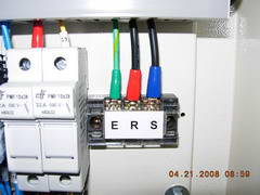
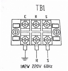
Earth Ground Wire
As we can clearly see in the photo above, the green terminal on the far left is definitely the connection point for the Earth Ground wire. This is also backed up and verified with the terminal block (TB1) drawing above on the right. The Earth Ground symbol is clearly identified.