|
Unless otherwise specifically permitted in the electrical code, the overcurrent protection for conductor types should not exceed the following: |
Although the preceding table is true and accurate, many times the wire type is not known. There are also instances where more than one type of wire is used on a circuit. This is why it is best to use this default chart to determine the capacity of the wire sizes listed below |
| Calculations for Wire Load Capacity are determined by using an 80% Load Factor. For example: The actual load capacity for a 20 amp #12 copper conductor would be 16 amps. Determined by using this formula: Amperage X .80 = Load Capacity or ( 20 X .80 = 16 ) |
| This table shows the Amperage Rating for Home Electrical Wire Sizes Although this is the most common table used to determine wire size, this is just one example. |
| Allowable Ampacity of Insulated Wire Conductors Based on NEC Table 310-16 |
| 60 Deg C (140 Deg F) |
75 Deg C (167 Deg F) |
90 Deg C (194 Deg F) |
60 Deg C (140 Deg F) |
75 Deg C (167 Deg F) |
90 Deg C (194 Deg F) |
|
| Wire Types |
TW, UF |
RHW, THHW, THW, THWN, XHHW | THHN, THWN-2, XHHW |
TW,UF | RHW, THHW, THW, THWN, XHHW | THHN, THWN-2, XHHW |
Wire Size |
| #14 | 20 | 20 | 25 | - | - | - |
| #12 | 25 | 25 | 30 | 20 | 20 | 25 |
| #10 | 30 | 35 | 40 | 25 | 30 | 35 |
| #8 | 40 | 50 | 55 | 30 | 40 | 45 |
| #6 | 55 | 65 | 75 | 40 | 50 | 60 |
| #4 | 70 | 85 | 95 | 55 | 65 | 75 |
| #3 | 85 | 100 | 110 | 65 | 75 | 85 |
| #2 | 95 | 115 | 130 | 75 | 90 | 100 |
| #1 | 110 | 130 | 150 | 85 | 100 | 115 |
|
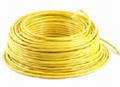
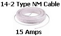
Type-NM Cable Used for House Wiring Copper Wire Conductors |
|
WIRE SIZE |
AMPERAGE |
#14 AWG |
15 Amps |
#12 AWG |
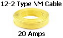
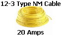
20 Amps |
#10 AWG |
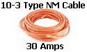
30 Amps |
#8 AWG |
40 Amps |
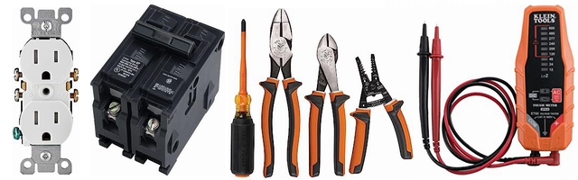
Common Electrical Wire for Home Circuit Wiring |
||
|---|---|---|
| Type NM Cable | Trade Name & Amps | Electrical Circuit |
|
|
 |
Wire for Outlets and Lighting |
 |
Wire for Lighting - 3-Way Switches and Smoke Detectors |
|
|
|
 |
Wire for Outlet Receptacles |
 |
3-Wire Circuits - Kitchen / Garage Wire | |
 |
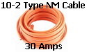 |
Wire for Water Heaters - Small A/C |
 |
Wire for Dryer with 4-Wire Receptacle | |
 |
 |
Wire for Small Ovens |
| Common Wiring Fasteners and Components and What They are Used For | ||
|---|---|---|
| WIRE PROTECTION | PART DESCRIPTION | WIRING PURPOSE and USE |
 |
Cable Staple Fasten cables to wood structure every 4-1/2' and within 8 " of boxes. |
7/16 - #14 Type NM Cable 9/16 - #12 & #10 Type NM Cable 1 - Inch for Larger Cables |
 |
Safety Plate | Protect the wires in vulnerable areas How to Home Wiring Projects |
| Common Wire Connectors and What They are Used For |
||
|---|---|---|
| WIRENUTS and WIRE CONNECTORS | WIRE CONNECTOR | CONNECTOR CAPACITY |
 |
Large Blue Wirenut | #14 thru #6 AWG Min. 3 #12 Max. 2 #6 w/ 1 #12 |
 |
Large Gray Wirenut | #18 to #6 AWG Min. 2 #12 Max. 6 #12 |
 |
Red Wirenut | #18 thru #8 AWG Min. 2 #18 Max. 4 #10 |
| Yellow Wirenut | #18 thru #10 AWG Min. 2 #18 Max. 3 #12 |
|
| Orange Wirenut | #22 to #14 AWG Min. 1 #18 w/ 1 #20 Max. 4 #16 w/ 1 #20 |
|
| Common Earth Grounding Components and What They are Used For |
||
|---|---|---|
| GROUND BONDING PART | PART DESCRIPTION | GROUND PURPOSE and USE |
 |
Crimp Sleeve | Joining two or three #14 or #12 bare ground wires to form a "tail" for bonding plugs & switches |
 |
Green Grounding Screw | Bond the ground wire using tapped ground access #14 and #12 wires |
 |
Grounding Clip | For older metal boxes without a ground screw access #14 and #12 wire |
 |
Ground Lug | Bonding larger wires various sizes for wires |
Remember to always check the device specifications for the Required Amperage and Circuit Breaker size, then select your home electrical wire size.
More about Electrical Wire |
Recent Questions and Comments
We have installed a 100 amp breaker box in a new work shop, what size breakers do I attach the main lines to in the 200amp box… I think a hardware store employee gave me wrong advice about cords. One side is smooth, one is ridged; which is which? Smooth side, ridged side: Which is which? |