» Home Electrical Wiring
» Electrical Wiring Directory
» Wiring Diagrams for Light Switches
» Need Electrical Help? Ask the Electrician
» Wiring Diagrams for Light Switches
» Need Electrical Help? Ask the Electrician
4-Way Switch Diagram

|
Summary:
Fully explained 4 way switch diagrams. 4-way switches are a convenient way to operate lighting fixtures from three or more locations. The electrical wiring adds additional wiring to the same principles of 3-way switching.
© By: Dave Rongey |
How to Wire a 4Way Switch
4 Way Switch Wiring
4-Way Switches provide switching from three or more locations.
If more than three switches are needed, simply place more 4-way switches between the three way switches.
IMPORTANT:
As you will see, most 4-way switch wiring is placed between the wiring of two 3-way switches, therefore a 4way switch is installed with two 3way switches.
InstructionsPlease Note: To illustrate the 4 way switch wiring, Switch boxes and Fixture boxes are not shown but are obviously required for every application. These diagrams are shown as using the Type NM Cable wiring method. These cables contain a ground conductor which is required for all applications as well. The ground conductors are always bonded together to insure the integrity of the ground path. If you are using metal boxes, the ground conductor must be attached to each box by using a threaded ground screw or provided attachment. The frames of the switches which have a ground screw are to be attached to the ground conductor as required. Please contact me if you have any questions or comments regarding these diagrams. |
Electrical Wire Connections to Switches and OutletsDo you recommend using push in type wire connectors? Also when using a dimmer in a 4 way switch circuit can you place the dimmer in any of the switch positions? Dave's reply: The push in connections are ok, except for 20 amp circuits or high load devices that will be used, especially with outlets. The function of a 4-way dimmer may depend on the type of dimmer you select and the switch wiring configuration as a whole. Lutron dimmers are great when multiple dimmers are required. Different Types of 4-Way SwitchesI was replacing a 4-way switch that seemed to be burned out on one pole and still had problems. After using your web sight and thinking through my problem, I realized that the old 4-way switches (about 23 years old) did not conform to current standards. The inputs and outputs were side to side, respectively, in stead of top and bottom as you show and how my new switch is designed. The old switch was labeled line 1 on one side to help with orientation. You can see the confusion this creates when you try to wire both an old style and new style switch in the same circuit. I eventually got it right! I thought you might want to make a comment somewhere on the page mentioning the different versions of these switches. Unrelated, but also annoying was that who ever wired the house used 14/2 instead of 14/3 travelers so they substituted the ground for neutral and the neutral for the red line just to confuse me more (the inspector must have been sleeping on the job unless this was allowed in the past). Thanks for maintaining this site. It saved me. Thank you Jim! Dave's Reply: Yes - there definitely is a difference with some 4-ways switches, especially the older ones. Great to hear you got them working. |
4-Way Switch Wiring Diagrams
This 4 way switch diagram #1 shows the power source starting at the left 3-way switch.
 |
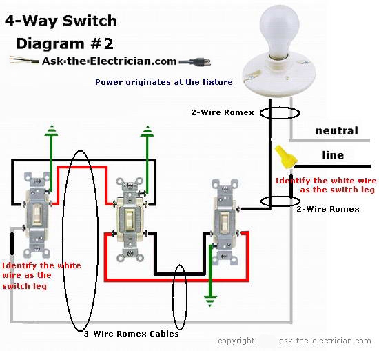
This 4 way switch diagram #2 shows the power source starting at the fixture.
The white wire of the cable going to the switch is attached to the black line in the fixture box using a wirenut. The white wire becomes the energized switch leg, as indicated by using black or red electrical tape.
More about Wiring a 4Way Switch
The Key to 4 Way Switch Wiring
- How to Wire a 4 Way Switch: My old 4-way light switch broke. I bought a new switch. The new switch has 4 terminals, two on either side, top and bottom.
Learn more about 4Way Switch Wiring
Wiring Four Way and Three Way Switches
- How to Wire Four Way and Three Way Switches with Helpful Wiring Diagrams…