Electrician Training Electrical Certification wiring recessed light fixtures Electrical Wiring Electrical Troubleshooting and Electrical Repairs wire outdoor light fixture Home Electrical Wiring Diagrams

wiring home generator and transfer switch wiring a 220 volt range cord outlet Wiring for GFCI Outlets Wiring Outlets and a Switched Outlet Wiring and Installing Ceiling Fans and Remote Controls wire dimmer switch wiring diagrams for switches wiring a dryer cord and 220 outlet circuit breaker panel
Electrical Wire and Cable
ask the electrician
Electrician Training Electrical Certification wiring recessed light fixtures Electrical Wiring Electrical Troubleshooting and Electrical Repairs wire outdoor light fixture Home Electrical Wiring Diagrams
wiring home generator and transfer switch wiring a 220 volt range cord outlet Wiring for GFCI Outlets Wiring Outlets and a Switched Outlet Installing and Wire Ceiling Fans and Remote Controls wire dimmer switch wiring diagrams for switches wiring a dryer cord and 220 outlet circuit breaker panel
Electrical Wire and Cable

GFCI Outlet Wiring Method


gfci outlet Summary: This article and the electrical wiring diagram will show you how to install a GFI using the feed through method which will protect more than one outlet.


GFI Wiring Diagram using the Feed Through Method


Electrical Wiring Video

Wire a GFCI Outlet without a Ground Wire

NOTE: A List of All my Helpful Videos

Will Display at the End of This Video

So Keep Watching So I Can Help You Wire it Right!


Check out my YouTube Channel:
» AskTheElectrician «
and Subscribe!


A typical application for this method would be to protect more than one bathroom, or the all of the receptacles in your garage. Below you will see some photos of recent projects that I have selected to help you with your project.

The GFCI Receptacle will have LINE and LOAD areas to attach your wires to. The "LINE" is the set of wires coming from the panel or power source, the "LOAD" is the wire set leaving the receptacle box to the other downstream receptacles to be controlled by the GFCI.

Protecting more than One Receptacle from One GFCI


This method is used when installing the GFCI as the first receptacle and wiring it so that it provides protection for all of the receptacles downstream on the circuit.

A typical application for this method would be to protect more than one bathroom, or the all of the receptacles in your garage.

Below you will see some photos of recent projects that I have selected to help you with your project.

The GFCI Receptacle will have LINE and LOAD areas to attach your wires to. The "LINE" is the set of wires coming from the panel or power source, the "LOAD" is the wire set leaving the receptacle box to the other downstream receptacles to be controlled by the GFCI.


Take a look at a typical Feed-Thought Installation
[Click on the images to Enlarge]

check local code reqs GFCI Feed Through Wiring 1 Pre-wiring for the feed through method
GFCI Feed Through Wiring 2 GFCI Feed Through Wiring 3 GFCI Feed Through Wiring 4
Label the electrical cable supplying the power. Folding the wires in until installation. This junction box is ready for the GFCI.
GFCI Feed Through Wiring 5 GFCI Feed Through Wiring 6 GFCI Feed Through Wiring 7
To install: fold wires out. Identify the set to be used for the LINE feed. Identify the LINE area of the GFCI Receptacle.
GFCI Feed Through Wiring 8 GFCI Feed Through Wiring 9 GFCI Feed Through Wiring 10
Remove the Yellow Warning sticker to expose the LOAD Area and Terminals. First attach the LINE Black wire to the LINE Hot Wire terminal, and the LINE White wire to the LINE White Wire Terminal. Now attach the LOAD Black wire to the LOAD Hot Wire terminal, and the LOAD White wire to the LOAD White Wire Terminal.
GFCI Feed Through Wiring 11 GFCI Feed Through Wiring 12 GFCI Feed Through Wiring 13
Fold the wires carefully back inside the receptacle box and install the GFCI receptacle. Mount the GFI cover plate. After all the downstream receptacles have been installed, the circuit is turned on and tested at all locations.

More about GFCI Outlets


Questions about GFCI Wiring

related

Overloaded GFI Outlet

Question: Chad, from Louisville, Kentucky asks:
I recently installed a new electrical outlet on a kitchen wall that previously had none. I basically ran the new wire down to our basement and tapped into an existing box that is running two additional outlets. I flipped the power on, plugged in the toaster oven and microwave and the clocks on both power up. However, when I run either of the two appliances, they tend to work for about 1-2 minutes and then stop. It doesn't trip the breaker, but the outlet simply quits working. Without doing anything, the outlet will turn itself back on after about 10 minutes or so (I know this as the clocks on the appliances power back up). I tried replacing the outlet with a GFI outlet and the same thing occurs only this time it does trip the GFI. Could it be the fact that I have plugged in two appliances that surge which is causing this to happen? Why would they work for a bit and then stop but then work again? I am very confused. Thanks. Chad

Answer: My first thought is to identify the circuit that you have tapped into and find out where that circuit originates from and if there could be any problems occurring with that circuit. As for the GFCI outlet, I have experienced where GFI outlets can act like a circuit breaker if the load that is passing though is too great. GFCI outlets do not do well when they are overloaded. You have not mentioned, but it may be that the GFI outlet is rated for 15 amps and the circuit is actually a 20 amp circuit. If this is the case then installing a 20 amp rated GFI outlet may solve the problem. Dave


How Many Outlets Can Connect to the first GFCI Outlet

Question: Using the feed through method, is there a limit on either the number of downstream receptacles or the distance beyond the GFCI outlet?

Answer: You can add any reasonable number of outlets, the concern is to stay within the amperage load of the circuit, distance is not a problem as long as your under 200 feet, depending on the connected types of load placed on the circuit. Dave


Double Quad Outlets Protected by GFCI

Question:This feed through is really good, but how would I wire it if it were a quad with a GFCI in the first position to protect all 3 standard down stream outlets? I would like to put in two quads. Would it be Line in from feed to GFCI, load out to second outlet (standard - non GFCI)in same box; then wire out from this standard non-GFCI to the second quad (2x standard non-GFCI)? Do I just use short wires to connect the outlets in each quad together? Thanks, Dan

Answer: Yes Dan, It's basically the same wiring as shown except that you are wiring the LOAD side out to all your outlets and they may be connected by making jumper wires or tails from each set to one connection for the LOAD Set of wires.


The Difference between a 15 Amp and 20 Amp GFCI

Question: Rob asks: How can I tell if the GFI outlet is a 15 or 20 amp outlet? Does it say on the outlet?

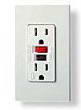
Answer: Yes - the GFCI Outlet should have a label or impression which states the voltage and amperage. You will also notice that on a 20 amp GFCI Outlet the left or neutral plug opening will have both the vertical and horizontal opening for a 20 amp plug. You may notice that with some brands of 15 amp GFCI Receptacles have a 20 amp rated feed through, therefore a 15 amp GFCI receptacle may be installed on a 20 amp circuit.

GFI Outlets Feeding Other Outlets

Question: Charlie Asks: I have seen the square outlets that have the same shape as a GFI. When installing downstream outlets from a GFI should these be used? This is new construction in Indiana. Thanks Charlie.

Answer: Dave's Reply: The square design that you are referring to for the other outlets is just a different decorative design and really does not have any significance to GFCI protection that is provided by the GFI outlet. The design of the GFI outlet was adopted most likely because of the extra space that was needed for the ground fault circuit components.


Hot Tub on a GFCI Outlet Circuit

Question: I hooked a GFCI receptacle to an existing circuit and it trips every once in a while. The GFCI is rated for 20 amps and it is protecting my new 12 amp hot tub. I replaced the GFCI, but still getting occasional tripping of the GFCI! Could the new hot tub be a lemon? Steve

Answer: Keep in mind that the existing circuit rating should be identified. Check to see if the hot tub requires it's own dedicated circuit. Sharing a circuit with a hot tub could cause nuisance tripping of a GFCI outlet if the circuit is loaded up to capacity. The hot tub could be tested for possible inconsistencies, and it may help to search for feedback about the reliability of the unit as well. Dave


More about Wiring GFCI Outlets


My Outlets Are Dead – Should I Replace The GFCI?

Fully explained wiring instructions complete with a picture series of GFCI installations and wiring diagrams can be found here…

GFCI Outlets and Aluminum Wire

How to Safely Wire GFCI Outlets: Creating a Copper Pig Tail with Aluminum Wire, Working with Aluminum Wire, Splicing Aluminum Wire, Anti-Corrosion Ointment for Aluminum Wire, Attaching Aluminum Wire, AL/CU Rated Outlets and Switches.

How To Wire a GFCI and Outlet to a Light Switch

Fully explained wiring instructions complete with a picture series of an installation and wiring diagrams can be found here in the GFI and Light Switch area here in this website. Just click the Wiring Diagrams…

Wiring a GFCI Outlet with a Switch

How to Wire a GFCI Outlet with a Switch – There are a few different methods that are used to wire GFI Outlets but all start with locating the Line side of the GFCI Receptacle where the power source is attached as described.

Hairdryer Outlet and GFI Safety Requirement

Electrical Protection Requirements for a Hairdryer Near a Sink – Keep in mind that if this outlet will be within 6 feet of a sink then the outlets require GFI protection.


Learn more about Wiring a GFCI Outlet


Electrical Questions about GFCI Feed Through Wiring Method


    Electrical Question:
    Why is the GFCI tester indicating that the Hot and neutral are reversed?

    Robert a Handyman from San Anselmo, California asks:
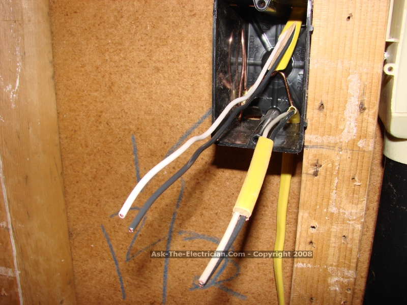
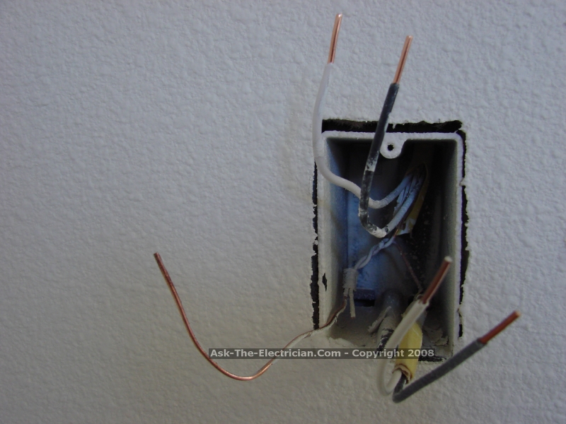
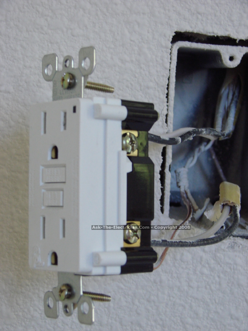
    We have wired thru a bathroom GFI out to a garage. Somewhere between the GFI and the wire in the garage the wiring has changed from Romex to the old style with 3 black stranded wire. I tried to wire a GFI into this wire making sure the hot went into the hot terminal, and determining that another wire was the neutral, and the third being the ground. When I install the GFI this way the tester shows that it is installed correctly until we push the GFI test button on the tester and then it says that the Hot and neutral are reversed. When you reverse these wires it still indicated that the hot and neutral are reversed. Any ideas?

    Answer:
    Make sure to verify the circuit wiring as it changes from Romex to the old style wiring. It would be best to replace the older wiring and upgrade the GFCI circuit.

» You Can Avoid Costly Mistakes! «
Here's How to Do It:
Wire It Right with the help of my Illustrated Wiring Book

Great for any Home Wiring Project.
  electrical wiring  

See How to Wire it Right!

Learn more about GFCI Outlet Wiring
Perfect for Homeowners, Students and Electricians
Includes:
Kitchen GFI Outlet Circuits
Bathroom GFI Outlet Circuits
Garage GFI Outlet Circuits
Hot Tub GFCI Circuits
Methods for Wiring GFCI Receptacle Outlets
Electrical Codes for GFCI Circuits and Receptacles
....and much more.

» Click here to learn more about Home Electrical Wiring «


Electrical Tips to Help You Wire it Right

The Safest Way to Test Electrical Devices and Identify Electric Wires!

The Non-Contact Electrical Tester
This is a testing tool that I have had in my personal electrical tool pouch for years, and is the first test tool I grab to help identify electrical wiring. It is a Non-contact tester that I use to easily Detect Voltage in Cables, Cords, Circuit Breakers, Lighting Fixtures, Switches, Outlets and Wires. Simply insert the end of the tester into an outlet, lamp socket, or hold the end of the tester against the wire you wish to test. Very handy and easy to use.

The Quickest Way to Check for Faulty Electrical Wiring!

The Plug-In Outlet Tester
This is the first tool I grab to troubleshoot a problem with outlet circuit wiring. This popular tester is also used by most inspectors to test for power and check the polarity of circuit wiring.
It detects probable improper wiring conditions in standard 110-125 VAC outlets Provides 6 probable wiring conditions that are quick and easy to read for ultimate efficiency Lights indicate if wiring is correct and indicator light chart is included Tests standard 3-wire outlets UL Listed Light indicates if wiring is incorrect Very handy and easy to use.

Strip Off Wire Insulation without Nicking and Damaging the Electric Wire!

The Wire Stripper and Wire Cutter
My absolute favorite wire stripping tool that I have had in my personal electrical tool pouch for years, and this is the tool I use to safely strip electrical wires.
This handy tool has multiple uses:
The wire gauges are shown on the side of the tool so you know which slot to use for stripping insulation.
The end of the tool can be used to grip and bend wire which is handy for attaching wire onto the screw terminals of switches and outlets..

The wire stripper will work on both solid and stranded wire. This tool is Very Handy and Easy to Use.

electrical parts

Residential Electrical Parts and Accessories


Light Switches

120volt Outlets

Circuit Breakers

Electrician Tools

Voltage Testers


RELATED


More about GFCI Feed Through Method

Causes Of Electrical Shock in Homes
What causes a shock when touching a light switch or water facet, how can this be fixed? How Incorrect Electrical Wiring Can Produce Electric Shocks.

Fix an Electrical Circuit for a Sump Pump or Septic Pump
My pump is not working and I am trying to troubleshoot the problem: How to Identify Typical Septic Pump Problems.

Why a Neutral Electrical Circuit Wire May Be Hot
What could be causing the copper ground and neutral wire be hot? Power went out in bathroom and I checked the circuit breaker, and the GFCI and it seems fine.

Cut Extension Cord Causes Power Loss to Outlets
How Can I Fix a Outlet that Lost Power after an Extension Cord Has Been Cut or Damaged? How to Locate and Restore the Power to an Outlet Circuit Has Lost Power.

Wiring Diagrams for 3-Way Switches
The Key to Wiring 3-Way Switches - The Power Feed and the Switch Leg leading to the fixture(s) typically, one at each switch location, are attached to the screw terminal found at one end of the switch by itself

Sitemap
Ceiling Fans Airplane Ceiling Fan Airplane Ceiling Fan Ceiling Fan Direction Summer Ceiling Fan Direction Winter Ceiling Fan Wiring Diagram 1 Ceiling Fan Wiring Diagram 2 Ceiling Fan Wiring Questions and Answers Ceiling Fans Wiring – Part 1 Ceiling Fans Wiring – Part 2 Introduction to Ceiling Fan Remote Controls Outdoor Ceiling Fan 1 Outdoor […]

Electrical Question about a Kitchen GFCI Outlet Circuit
I have several electrical outlets in my kitchen, all marked GFCI; however, only 2 of them have a trip/reset button.

Electrical Question about a Receptacle at the End of a Line
I have a receptacle at the end of a line with 1 set of wires coming into the wall box, that I want to make into a blank wall plate

GFCI Feed Through Method - 1741