


How to Wire a JVR Digital Time Switch

|
How can I wire a JVR Digital Time Switch? Wiring a Circuit for a JVR TL34 Digital Time Switch. © By: Dave Rongey |
Wiring a JVR Timer
Electrical Question: How can I wire a JVR Digital Time Switch?
Wiring a Timer Switch
Paola asks:
- I am trying to connect a timer to an electromagnet.
- The electromagnet needs a charge of 9v, and the timer says 12v.
Additional Comments: The page is very helpful!
Dave’s Reply:
Thanks for your electrical wiring question Paola.
How to Wire a JVR Digital Timer Switch
Application: Wiring a Digital Timer Switch.
Skill Level: Beginner to Intermediate – Best performed by a Licensed Electrical Contractor, or Certified Electrician.
Electrical Tools Required: Basic Electricians Pouch Hand Tools, Voltage Tester, and appropriate Safety Gear.
Estimated Time: Depends on the personal level experience, ability to work with tools, install electrical circuit wiring, and the available access to the project area.
Electrical Safety: Identify the electrical power source to the Timer Switch, turn it OFF and Tag with a Note before working with the electrical wiring.
Electrical Wiring Parts and Materials: Electrical parts and materials for the Timer Switch should be approved for the specific project and compliant with local and national electrical codes.
Wire a Circuit for a JVR TL34 Digital Time Switch
This electrical wiring project is about Wiring a Circuit for a Timer Switch in the Shed of a Home.
Timer Switch Wire a Circuit
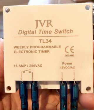
Paola, from the information you have provided, the JVR TL34 Digital Time Switch needs a 12V power supply on terminals 3 and 4 to make the timer work. This could be from a 12V car battery or a plug in power adapter with an output of 12V which should be provided with the JVR Timer. The terminals 1 and 2 can be used to control a load of up to 250volt 16amps, and the normal state of the contacts is normally open, which means whatever is connected to terminals 1 and 2 will not turn on unless the set time has been achieved. Terminals 1 and 2 are nothing more than pair of contacts just like that of a light switch. If you want to control the electromagnet then a power supply must be provided for it, and the positive power wire is wired through terminals 1 and 2. NOTE: The required power for the electromagnet must be less than 250volt 16amps, which is the rating for the contacts on the time switch.
More about Wiring Switches

Wiring a Light Switch – Diagram 1
Wiring Diagrams
Fully Explained Light Switch Wiring Diagrams. Detailed Electrical Wiring Diagrams and Pictures assist your Home Electrical Projects.
Electrical Wire for the Home
Complete listing of electrical wire types and parts used for home projects with electrical code information serves as selection guidelines.

Electric Circuit Listing
The size of the home electrical service panel and the electrical circuits is designed by calculating the square footage of the home and factoring in the code requirements for the electrical circuits that are required.
The following may also be helpful for you:

The Safest Way to Test Electrical Devices and Identify Electric Wires!The Non-Contact Electrical TesterThis is a testing tool that I have had in my personal electrical tool pouch for years, and is the first test tool I grab to help identify electrical wiring. It is a Non-contact tester that I use to easily Detect Voltage in Cables, Cords, Circuit Breakers, Lighting Fixtures, Switches, Outlets and Wires. Simply insert the end of the tester into an outlet, lamp socket, or hold the end of the tester against the wire you wish to test. Very handy and easy to use.
The Quickest Way to Check for Faulty Electrical Wiring!The Plug-In Outlet TesterThis is the first tool I grab to troubleshoot a problem with outlet circuit wiring. This popular tester is also used by most inspectors to test for power and check the polarity of circuit wiring. It detects probable improper wiring conditions in standard 110-125 VAC outlets Provides 6 probable wiring conditions that are quick and easy to read for ultimate efficiency Lights indicate if wiring is correct and indicator light chart is included Tests standard 3-wire outlets UL Listed Light indicates if wiring is incorrect Very handy and easy to use.
Strip Off Wire Insulation without Nicking and Damaging the Electric Wire!The Wire Stripper and Wire CutterMy absolute favorite wire stripping tool that I have had in my personal electrical tool pouch for years, and this is the tool I use to safely strip electrical wires. This handy tool has multiple uses: The wire gauges are shown on the side of the tool so you know which slot to use for stripping insulation. The end of the tool can be used to grip and bend wire which is handy for attaching wire onto the screw terminals of switches and outlets.. The wire stripper will work on both solid and stranded wire. This tool is Very Handy and Easy to Use. |
||


Switches Parts and AccessoriesLight Switch Single Pole 3 Way Light Switch 4 Way Light Switch Switch and Outlet Combo Dimmer Switch |
Be Careful and Be Safe - Never Work on Energized Circuits!
Consult your Local Building Department about Permits and Inspections for all Electric Wiring Projects.
More articles about Electrical Wiring and Home Electrical Wiring: |
|
| « Previous | Next » |
Electric Circuit Repair after Flood or Water Damage |
Electric Wiring for AFCI in a Home |


