


How to Test Electrical Circuits for a Home Generator

|
Home Generator Circuits Explained – Electrical load testing for home generator circuits can produce some puzzling results, especially when measuring incandescent lighting loads and other 120 volt circuit loads. © By: Dave Rongey |
Understanding Home Generator Circuits
Home Electrical Troubleshooting Repairs Question: When testing a Cutler Hammer 8 space main lug sub panel for its current usage (for a generator set up)with a Greenlee digital “Amprobe”, I detected 37 amps on one supply leg, 25 amps on the other supply leg, and 12 amps going through the leg to ground.
- I do not understand the 12 amps going to ground, what the source of the “ground” might be, or how to find the problem if in fact it is a problem.
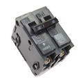
- There is a 100 amp double pole breaker used as the “main” for the sub panel itself, a 30 amp double pole breaker for a water heater, and four 20 amp single pole breakers for lighting.
- The water heater lines tested 17 amps each, which i consider reasonable usage (did not notice the size of the water heater)….the 4 lighting circuits tested 2 to 3 amps each- a conglomeration of incandescent and CFL bulbs are on those circuits.
Can you shed some light on this one for me? (no pun intended)
This home electrical repairs question came from: TOM, from Oaks, Pennsylvania
Dave’s Reply:
Thanks for your electrical troubleshooting question TOM
Home Generator Circuits Explained
Testing Generator Circuits
- Electrical load testing for home generator circuits can produce some puzzling results, especially when measuring incandescent lighting loads and other 120 volt circuit loads.
- As described in this question you will notice that the ground connection for the main generator is also serving as the neutral for the 120 volt circuits.
- The 20 amp 120 volt circuits are providing power for the incandescent lighting circuits, therefore the 12 amp reading on the ground wire may be due to the incandescent lighting loads of the 120 volt circuits where the return power is being measured at 12 amps.
- You can verify this by measuring the amperage of the ground and turning off one or more of the 20 amp lighting circuits and you should notice the amperage drop down if the incandescent lighting is in fact being used at the time of the test.
- Make sure that the ground and neutral system of the generator and main panel are properly bonded. When connecting 120/240 volt circuit loads to a generator it is best if the generator has a 4-wire connection.
- IMPORTANT: All generator power connections must be made using an approved transfer switch or approved circuit interlock device to safely allow only one source of power at any given time and provide a disconnection from the main electric utility company power source.
More about Home Generators and Electrical Testing
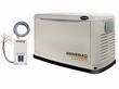
Home Electric Generators
This series covers a wide variety of topics all about home generators including sizing, selecting, connecting and safely operating this all important addition to your home.
Generator Section
The Importance of a Generator Transfer Switch
Generator Articles
Generator Questions and Answers

House Wiring Circuits and Circuit Breakers
This article looks at common 120 volt and 240 volt house wiring circuits and the circuit breakers that are installed identifying the types and amperage sizes used in most homes
Electrical Panel Circuit Listing

Electric Circuit Listing
The size of the home electrical service panel is designed by calculating the square footage of the home and factoring in the code requirements for the electrical circuits that are required.
Home Electrical Circuit Breakers
Home Electrical Circuit Breakers
A guide to home electrical circuit breakers and how they work to protect your electrical wiring. When properly installed, your home electrical wiring is protected by a circuit protection device.

Planning and Installing Home Lighting
Home lighting articles covering recessed lighting, under cabinet lighting, lighting terminology and more.
How to Install Home Lighting
Lighting Electrical Codes
Using Testers to Identify Electrical Problems
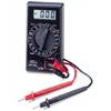
Testers to Help Solve Electrical Problems
Troubleshooting Electrical Wiring
Types of Electrical Testers
Using Electrical Testers
The following may also be helpful for you:
Be Careful and Be Safe - Never Work on Energized Circuits!
Consult your Local Building Department about Permits and Inspections for all Electric Wiring Projects.
More articles about Electrical Repair, Electrical Wiring, Generators and Home Electrical Wiring: |
|
| « Previous | Next » |
Home Generator Automatic Transfer Switch Design |
Grounds and Neutrals in Electrical Panel |


