


What to do about Stray Electrical Voltage Readings

|
How to Identify the Source of Stray Voltage: Stray Electrical Voltage Readings Should be Identified and Corrected Right Away – Stray voltage is not normal and may originate from a faulty electrical or electronic component that could potentially become a serious shock hazard and cause damage to equipment. © By: Dave Rongey |
Sources of Stray Electrical Voltage
Electrical Troubleshooting Question: I have a single jet water pump motor, 120volt, on my inside spa that was wired by a licensed electrician 10 years ago. It has a dedicated circuit with a GFCI circuit breaker.
- Recently I started having problems with the motor starting and replaced the capacitor but that did not help.
- I measured the voltage at the power outlet and sometimes it is 112volt and at other times 120volt.
- When I do get the spa to run, the outside metal conduit from the outlet to the breaker panel reads 6 volts by touching one meter probe to the conduit and the other probe stuck into the earth ground (dirt). It is possible that an internal wire is frayed and leaking voltage to the metal conduit?
- The spa technician checked the spa and said everything was running fine.
- The HVAC electrician checking my furnace before winter suggested that a frayed wire maybe at a corner bend could be the problem.
- Interestingly, the GFCI has never tripped. Is 6 volts on the metal conduit normal and could this be the cause of the lower outlet voltage and a future electrical hazard?
This home electrical repairs question came from: Bob, from Las Vegas, Nevada.
Additional Comments: This is a great reference site and I have it in my favorites, but I currently have an unusual situation not covered.
Dave’s Reply:
Thanks for your electrical troubleshooting question Bob.
How to Identify the Source of Stray Voltage
Bob, the indication of problems with the pump motor would be an indication and possible source of the voltage readings, however because the GFCI protection is not tripping this leads me to question the home ground system, please read on.
Skill Level: Intermediate to Advanced – Licensed Electrical Contractor, Not Recommended for Homeowners.
Tools Required: Electricians Pouch of Hand Tools.
Estimated Time: Depends on the extent of the project, the grounding method to be inspected and available access to the project area.
Precaution: If the only ground source for the electrical system will be modified or repaired then the electrical service should be shut off until the new ground source can be reconnected.
Notice: Making changes to the Electrical Service Panel and Ground Electrode System should be done with a permit and be inspected.
Stray Electrical Voltage Readings Should be Identified and Corrected Right Away
- Stray voltage is not normal and may originate from a faulty electrical or electronic component that could potentially become a serious shock hazard and cause damage to equipment, however stray voltage may also be an indication that the home electrical ground system has not been installed correctly or may not be bonded properly which could prevent GFCI or ground fault sensing devices to not perform correctly.
- The priority should be to have the home electrical ground system examined and make any necessary repairs as needed.
- If the home ground system was in need of repair then this may cause GFCI devices to perform properly or even circuit breakers to trip OFF which will help to identify the source of the stray voltage.
This Procedure will help Locate the Source of Stray Voltage
- Attach a voltage meter to the equipment or parts where the stray voltage has been a problem or suspected, attaching one test lead to the equipment and one test lead to the ground or a grounded source.
- Begin turning OFF each circuit breaker at the main electrical panel until the stray voltage reading is no longer present.
- Identify what the circuit is being used for and note weather it is a dedicated circuit to specific equipment, and if so the electrical components components will need to be tested.
- If the circuit feeds several devices then they will all have to be identified.
Pin Point the Stray Voltage Produced by Equipment or Connected Circuit Devices
- Keep the identified circuit turned OFF and Isolate the equipment or each device from the circuit to prevent false readings and repeat the same test process but instead use a continuity meter to test the circuit lead wires and measure resistance to the ground, individually testing each device or equipment lead wire one at a time.
- This should allow you to be more specific about the cause of the stray voltage which will then enable you to arrange to perform the necessary electrical repairs or have the faulty components or equipment replaced.
Potential Sources of Stray Voltage
- Stray voltage may be found in areas where there are electrical devices or equipment in areas that are damp or wet, therefore stray voltage may be more prevalent in the wet winter months than in the warm summer months.
- Stray voltage should never be a natural occurrence when electrical wiring and devices have been installed correctly and according to code.
More about Electrical Wiring

House Wiring Circuits and Circuit Breakers
This article looks at common 120 volt and 240 volt house wiring circuits and the circuit breakers that are installed identifying the types and amperage sizes used in most homes.
Electrical Panel Circuit Listing

Electrical Circuit Wiring
This article looks at common 120 volt and 240 volt house wiring circuits and the circuit breakers that are installed identifying the types and amperage sizes used in most homes.
Home Electrical Panel Circuit Listing
Home Electrical Circuit Breakers
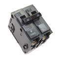
Home Electrical Circuit Breakers
A guide to home electrical circuit breakers and how they work to protect your electrical wiring. When properly installed, your home electrical wiring is protected by a circuit protection device.

Spa Tub Circuit Wiring
Electrical Codes and details for Spa and Hot Tub electrical wiring. Essentials for your hot tub installation, including the required GFCI ground fault protection and circuit wire size.

Wiring a GFCI Outlet
This list of articles will help you learn about the features and benefits provided by GFI and GFCI Receptacles and how they are wired.
Using Electrical Testers and Voltage Meters
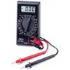
Understanding Digital Volt Meters
When working on home electrical wiring using voltage meter can play an important part in electrical safety. Electrical testers and voltage meters enable you to identify electrical circuits and help prevent the possibility of accidental electrical shock.
Types of Electrical Testers
Using Electrical Testers and Voltage Meters
The following may also be helpful for you:
Be Careful and Be Safe - Never Work on Energized Circuits!
Consult your Local Building Department about Permits and Inspections for all Electric Wiring Projects.
More articles about Electrical Repair and Home Electrical Wiring: |
|
| « Previous | Next » |
Wiring Two Power Sources for a Submersible Pump |
Ceiling Fan With Flashing Light Problem |


