The Process for removing the tab link from the outlet |
|
| This series of electrical wiring pictures shows how the actual wiring is attached using the top wiring diagram scenario #1 where the power enters at the switch box and a 3-wire romex runs from the switch box down to the grounded wall outlet. | |
 |
Step OneThe circuit has been positively identified and the power has been shut off. A note has been placed to let others know that there is work being done on the circuit. |
 |
Step TwoRemove the caps or wire nuts off of the wires. Strip the insulation from the insulated wires according to the strip gauge on the back of the outlet. Use you wire strippers or pliers to make a hook on the end of the ground wire so it can be attached to the ground screw of the outlet. |
 |
Step ThreeHere is the bridge or tab that joins the upper and lower sections of the power side of the outlet together. This is a flat brass piece of metal. |
 |
Step FourBy using a pair of needle nose pliers you can grip the flat tab of metal and with a side to side motion wiggle it back and forth until it breaks off. Side cutters are sometimes used but that can leave the metal in place or sticking out where it can become a problem. |
 |
Step FiveHere the tab is removed and now the top and bottom outlets are separated from one another. |
 |
Step SixNotice that the two separate colored wires, red for the light fixtures which is controlled by the switch and the black for the bottom outlet which is hot all the time. Notice that I have used the quick connect because the lighting load is small. If the load was greater then I would have attached the wires to the screw terminals on the side. |
 |
Step SevenThe wiring is folded back into the outlet box being careful that the ground wire is not near the screws of the outlet's hot or neutral side. |
 |
Step EightUse the outlet mounting screws to secure the outlet firmly to the wall adjusting the outlet from side to side as necessary, depending on how well of a job the sheet rockers have done. |
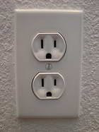 |
Step NineMount the cover plate in place, notice the opening to the box is complete covered up. This electrical project is complete and ready for the power to be restored to the circuit. |
How to Wire A Switched Outlet

|
Summary: Step-By-Step Procedure that must be performed for Switch wed Outlets to Function. One very important element can be easily overlooked as you will see in these pictures.
© By: Dave Rongey |
Switched Outlet Wiring and Tab Removal Procedure
This electrical picture series shows the vital procedure that must be performed in order for the switched outlet to work. If this procedure is not done then the most typical problem will be that both upper and lower outlet will be hot instead of one being controlled by the wall switch.
When this procedure is done correctly it will produce a switched outlet also known as a Half Hot Plug. This procedure shows how the outlets have the tab removed from the "hot" side or Brass side of the outlet which allows the top half of the plug to be controlled only from the switch while the bottom end of the outlet remains "hot" all the time. This is shown in the pictures below.