


Control Switch Wiring for a In-Line Exhaust Fan

|
How is a switch wired for an Bathroom Exhaust Fan? How to Wire a Switch for an Inline Exhaust Fan. © By: Dave Rongey |
Wire a Switch for an Exhaust Fan
Electrical Question: How is a switch wired for an Bathroom Exhaust Fan?
- I have a inline exhaust fan that Y’s and goes to each of my bathrooms. In this order from the fan motor there is a variable speed control and a low voltage transformer. Off of the transformer there is low voltage wiring (4 wire, but only 2 are being used) that runs to my master bath.
- Then from the master bath there is a separate line (4 wire low voltage) running to my main level bathroom. To me it looks like the switches are meant to be hooked up in series.
- There were never any switch installed when I purchased the house.
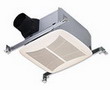
My question is what timer or controller do I need with it being low voltage wiring running to each box in each bathroom? The inline fan is a Fantech FR110.
This electrical wiring question came from: Greg, a Handyman from Saint Cloud, Minnesota.
Additional Comments: Very informational
Dave’s Reply:
Thanks for your electrical wiring question Greg
How to Wire a Switch for an Inline Exhaust Fan
This applies to Some Regular Exhaust Fans and Inline Exhaust Fans
Application:
Low Voltage Switch Controls for an In-Line Exhaust Fan
Low Voltage Control Switch Wiring for an In-Line Exhaust Fan
Greg, this is a great question and the person who installed this in-line bathroom exhaust fan had a very good idea, as long as the exhaust fan is rated large enough for the square footage and required air exchanges of both bathrooms.
The low voltage control wiring is relatively simple. Understand that low voltage controls are simply a smaller control circuit that activates a larger control relay or contractor. In this case the control wiring is the same for one, two or even more switches located in each bathroom. As you mentioned, there is a low voltage power supply, which will supply power for the control relay. Each pair of wires will act as a switch to control one side of the low voltage power. The low voltage relay is located near the in-line exhaust fan where it will act as a switch for the 120 volt power for the in-line exhaust fan. The low voltage wires are simply wired to a single pole switch. When one or both switches are activated they will in turn activate the control relay which will then turn on the in-line exhaust fan.
Key Components for a Low Voltage Control System
The low voltage wiring may be installed into an existing junction box if the wiring is rated for 600 volts, which is the rating for typical electrical cable. If the low voltage wiring is not rated for 600 volts then a partition must be installed into the junction box being shared, or a separate switch box must be installed for the low voltage switch and wiring.
The low voltage power supply and control relay must be installed in an accessible area and in an approved electrical junction box or electrical enclosure.
The low voltage wiring and the 120 volt circuit wiring must all be installed according to code.
As always, a project like this must be installed with a permit and inspected.
More about Wiring Switches and Relays:

Understanding Electrical Relays
The use of relays that are sometimes needed to control special device loads such as Air Conditioners and other high demand equipment from starting at the same time.

Wiring a Light Switch – Diagram 1
Fully Explained Light Switch Wiring Diagrams. Detailed Electrical Wiring Diagrams and Pictures assist your Home Electrical Projects.
How to Install Bathroom Electrical Wiring
Bathroom Electrical Wiring
Fully Explained Photos and Wiring Diagrams for Bathroom Electrical Wiring with Code Requirements for most new or remodel projects.
The following may also be helpful for you:
Be Careful and Be Safe - Never Work on Energized Circuits!
Consult your Local Building Department about Permits and Inspections for all Electric Wiring Projects.
More articles about Exhaust Fan Wiring and Home Electrical Wiring: |
|
| « Previous | Next » |
Wire Size for a Home Electrical Service Panel |
Identify Light Fixture Wiring |


