Electrician Training Electrical Certification wiring recessed light fixtures Electrical Wiring Electrical Troubleshooting and Electrical Repairs wire outdoor light fixture Home Electrical Wiring Diagrams

wiring home generator and transfer switch wiring a 220 volt range cord outlet Wiring for GFCI Outlets Wiring Outlets and a Switched Outlet Wiring and Installing Ceiling Fans and Remote Controls wire dimmer switch wiring diagrams for switches wiring a dryer cord and 220 outlet circuit breaker panel
Electrical Wire and Cable
ask the electrician
Electrician Training Electrical Certification wiring recessed light fixtures Electrical Wiring Electrical Troubleshooting and Electrical Repairs wire outdoor light fixture Home Electrical Wiring Diagrams
wiring home generator and transfer switch wiring a 220 volt range cord outlet Wiring for GFCI Outlets Wiring Outlets and a Switched Outlet How to Installing and Wire Ceiling Fans and Remote Controls wire dimmer switch wiring diagrams for switches wiring a dryer cord and 220 outlet circuit breaker panel
Electrical Wire and Cable

Basic Engine Components

car-electrical-systems
By
Summary: Identifying Basic Engine Components and their function.

Identifying Basic Engine Components


Lets take a look at Basic Engine Components.


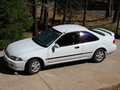
EXAMPLE: Engine System Components of a 1994 Honda Civic.

Typical Basic Engine Components

Here are the Basic Engine Components you'll need to identify for your car.


* PLEASE NOTE This discussion is limited to this particular car. Your car might be different. Verify the exact wiring for your application requirements.
Wiring Table

Basic Engine Components

Under the Hood - Engine Area

Basic-Engine-Components-Identified

The Basic Engine Components Identified in this photo include:

  • The air intake tube that leads to the air cleaner.
  • The throttle body where air enters the engine of the car.
  • The accelerator which is controlled by the gas pedal and controls the speed of the engine.
  • The gas line that supplies fuel from the gas tank to the engine.
  • The fuel injection assembly which distributes the fuel and air mixture into the engine cylinders.
  • The valve cover over the top of the cylinders of the engine.
  • The spark plugs and set of wires that provide ignition for the cylinders.
  • The distributor cap containing the rotor which sends electrical power to each spark plug.
  • The oil inlet cap where oil is added to keep the engine lubricated.
  • I Hope this Description of Basic Engine Components Helps You!


    » You Can Avoid Costly Mistakes! «

    Here's How to Do It:
    Wire It Right with the help of my Illustrated Wiring Book

    Great for any Home Electric Wiring Project.

    See How to Wire it Right!

    Learn about How to Wire a House
    Complete Guide to Home Electrical Wiring
    Perfect for the Homeowner, Handyman,
    Electrician and Building Inspector.

    Includes:
    Home Electrical Wiring - Room by Room
    Wiring Outlets
    Wiring Light Switches
    Wiring 120 Volt Circuits
    Wiring 240 Volt Circuits
    Multi-Wired Circuits
    Methods for Installing Home Electric Wiring
    NEC Codes for Home Electrical Wiring
    ....and much more.

    » Click here to learn more about Home Electrical Wiring «
      electrical wiring
    Home Wiring Book


    Electrical Tips to Help You Wire it Right

    The Safest Way to Test Electrical Devices and Identify Electric Wires!

    The Non-Contact Electrical Tester
    This is a testing tool that I have had in my personal electrical tool pouch for years, and is the first test tool I grab to help identify electrical wiring. It is a Non-contact tester that I use to easily Detect Voltage in Cables, Cords, Circuit Breakers, Lighting Fixtures, Switches, Outlets and Wires. Simply insert the end of the tester into an outlet, lamp socket, or hold the end of the tester against the wire you wish to test. Very handy and easy to use.

    The Quickest Way to Check for Faulty Electrical Wiring!

    The Plug-In Outlet Tester
    This is the first tool I grab to troubleshoot a problem with outlet circuit wiring. This popular tester is also used by most inspectors to test for power and check the polarity of circuit wiring.
    It detects probable improper wiring conditions in standard 110-125 VAC outlets Provides 6 probable wiring conditions that are quick and easy to read for ultimate efficiency Lights indicate if wiring is correct and indicator light chart is included Tests standard 3-wire outlets UL Listed Light indicates if wiring is incorrect Very handy and easy to use.

    Strip Off Wire Insulation without Nicking and Damaging the Electric Wire!

    The Wire Stripper and Wire Cutter
    My absolute favorite wire stripping tool that I have had in my personal electrical tool pouch for years, and this is the tool I use to safely strip electrical wires.
    This handy tool has multiple uses:
    The wire gauges are shown on the side of the tool so you know which slot to use for stripping insulation.
    The end of the tool can be used to grip and bend wire which is handy for attaching wire onto the screw terminals of switches and outlets..

    The wire stripper will work on both solid and stranded wire. This tool is Very Handy and Easy to Use.


    RELATED


    More about Engine components

    Sitemap
    220 volt circuit questions Why Circuit Breakers Trip Off and What To Do Next Installing 220Volt for a Range and Dryer in a Basement 220 Volt Wiring 220 240 Volt Air Compressor Wiring Electric Water Heater Wiring and Video How to Install a Whole House Humidifier Circuit Converting a 120 Volt Motor to 240 Volts […]

    How to Correct Low Voltage Conditions
    How Single Phase Voltage Regulators Work to Correct Abnormal Voltage Conditions: Single Phase Servo Voltage Regulators determine automatically the change in voltage as the constant voltage. This is accomplished by using electro-mechanic, passive or active components. The Servo Voltage Regulator makes the comparison between the real output voltage and the inner reference voltages.

    Electrical Wiring Diagrams and Symbols
    Identifying Electrical Diagram Symbols: Electrical symbols are used to identify the various components that are used when installing electrical circuits and devices - The electrical symbols for outlets switches light fixtures panels and more.

    engine components - 1027