


How to Wire a 3 Phase Air Compressor

|
How is an air compressor wired and where do the wires go? Wiring a 3 Phase Motor for an Air Compressor, The Basic Requirements for Wiring Electric Motors, 3 Phase Motor Circuits. © By: Dave Rongey |
Air Compressor Electric Motor
Electrical Question: How is a 3 phase air compressor wired and where do the wires go?
- We have a Saylor Beall air compressor we are trying to get wired up.
- It ran fine at the previous shop and then we moved it to this shop.
- The motor is 3 phase and it appears to be wired according to the diagram for the low voltage 220.
- The label shows that it can be wired for 220 or 460. It is all wired and hooked up to the controller, but here is where we are having problems, we cant get it to start, it only hums.
- The motor starter is a Cutler Hammer # A10CNO. The wires from our shop circuit breaker has 2 yellow hot wires at 120 volts each, 1 white neutral wire and 1 green ground wire.
- Is it possible to wire the compressor with this combination of wires and where do they go?
- When the compressor was moved it was simply unplugged from the wall and moved, all pressure switches and motor wires are in their same locations as before.
This electrical wiring question came from Cody in Enid, Oklahoma.
Dave’s Reply:
Thanks for your electrical wiring question Cody.
Wiring a 3 Phase Motor for an Air Compressor

The Basic Requirements for Wiring Electric Motors
- Every motor should have a name plate which is typically attached on the side or end of the motor. The information found on the label tells all about the motor size and electrical requirements. To stay on track with this question, the shop where the motor is to be installed must have an electrical service which supplies either 3 phase 230 volts, or 3 phase 460 volts.
Electrical Service Panels
- Just like electric motors, an electrical service panel should be equipped with a label which is attached either on the cover or inside the door. The information on this label will be specific to the make and model of the electrical panel along with the voltage and amperage rating. Here in the USA, a typical home electrical panel may be 120/240 volts 125 amps. The actual amperage capacity of the panel is best known by examining the Main Disconnect or Main Circuit Breaker, which will have the amperage rating identified, such as on the breaker handle.
Electrical Power for 3 Phase Motors
- Without getting too technical, a 3 phase electrical service panel will produce 3 separate lines of electrical power. A 120/240 volt single phase panel found at a home or shop can only provide up to two separate lines of power, therefore this type of electrical service could not provide the necessary power for a 3 phase motor.
3 Phase Motor Starters and Control Circuits
- As described above, a typical 3 phase motor circuit will have 3 separate insulated wire conductors for the power and the ground wire. A neutral wire is not required for a 3 phase motor.

- Wiring Electrical Control Relays
- How to wire control relays for equipment such as Generators, Air Conditioners, Heating Furnace, and other high demand equipment. Full explanation describing the principles which are easily adapted to residential wiring applications.
More about Wiring Electrical Control Relays
A Summary of Wiring 3 Phase Motors
- Identify the required voltage and amperage.
- Determine if the electrical service panel has the same voltage and available amperage capacity.
- Electric motors are typically wired to a motor controller or motor starter which is sized appropriately to the horsepower of the motor and has thermal overload protection.
More about Electrical Circuit Wiring

House Wiring Circuits and Circuit Breakers
This article looks at common 120 volt and 240 volt house wiring circuits and the circuit breakers that are installed identifying the types and amperage sizes used in most homes.
Electrical Panel Circuit Listing
- Electrical Codes for Home Wiring
- Electrician Explains Home Electrical Wiring Codes including AFCI Circuit, Junction Boxes, Electrical Circuits, Codes for Outlets, GFCI Codes, Electrical Grounding, Electrical Projects, Electrical Service Panels, Underground Electrical, House Wiring, Lighting Codes, Codes for Smoke Detectors.
More about Electrical Codes For Home Wiring
Home Electrical Circuit Breakers
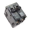
Home Electrical Circuit Breakers
A guide to home electrical circuit breakers and how they work to protect your electrical wiring. When properly installed, your home electrical wiring is protected by a circuit protection device.
The following may also be helpful for you:
Be Careful and Be Safe - Never Work on Energized Circuits!
Consult your Local Building Department about Permits and Inspections for all Electric Wiring Projects.
More articles about Electrical Wiring and Home Electrical Wiring: |
|
| « Previous | Next » |
Understanding Automatic Gate Opening Systems |
Wiring Ceiling Fans for Wall Switches |


