Electrical Question from Rowell about Electrical Wiring
Question: How do I identify home electrical problems and then decide the correct solution?
Dave’s Reply:
Magandang umaga my Filipino Friend, Salamat Po – Thanks for your electrical question Rowell. When an electrical circuit or device fails the best way to determine what has caused the problem is to begin troubleshooting using the process of elimination. Please follow the link below for Troubleshooting Electrical Wiring Problems. (This electrical question is from the Philippines.)
The Following links will assist you with your electrical question:
Troubleshooting Electrical Wiring Problems
For more information about Electrical Wiring
Electrical Wiring
This link is helpful as a Contractor
Electrical Code Articles
Make sure not to miss these Resources for: Wiring Diagrams
Wiring Diagrams
Be Careful and Be Safe – Never Work on Energized Circuits!
For Best Results Consult a Licensed Electrical Contractor.
Locate An Electrical Contractor in Your Area
Wiring a 3 Prong Dryer Cord
Electrical Question: I have an electric dryer with a 3 prong cord but my wall outlet is a 4 prong.
- I bought a 4 prong cord to switch out but before I installed it on dryer I wanted to make sure plug would fit. (I who knows nothing about electrical wiring or dangers).
- The cord was on the ground with all 4 wires exposed when I plugged it into the outlet. Of course it arced and fried the ring terminals.
- I turned off the circuit breaker to unplug the cord. I realize I could have fried myself now but my question is now that the new 4 prong cord has been installed on dryer and we plug it in, it does not work. Did I fry the plug?
Background: Toni, from Santa Cruz, California.
Additional Comments: Your website was helpful in showing me how to switch out a 3 prong to a 4 prong dryer cord.
Dave’s Reply:
Thanks for your electric wiring question Toni.
Connecting 3Wire and 4Wire Dryer Cords
Application: How to Wire a 3Prong Cord for an Electric Dryer, How to wire a 4 prong dryer plug.
Skill Level: Intermediate to Advanced. This electrical project is best performed by a Licensed Electrician or Electrical Contractor or Certified Electrician.
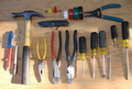
Tools Required: Basic Electricians Pouch Hand Tools and Voltage Tester.
Estimated Time: Depends on personal level experience, ability to work with tools and connect the 240 volt dryer cord.
Precaution: Identify the dryer circuit at the electric panel, turn it OFF and Tag it with a Note before working with the dryer cord wiring.
Notice: Wiring a electric dryer cord and making the electrical connections should be done according to local and national electrical codes and using approved materials.
How to Hook Up a 3Wire and 4Wire Dryer Cord
- Safety First – Unplug the Dryer Cord
- Always make sure the dryer cord is not plugged into the receptacle when making the wiring connections.
- Damage from Shorted Wires
- NOTE: As with this question, shorted wires typically do not damaged the 220 volt receptacle outlet.
- Resetting the Dryer Circuit
- If the dryer circuit breaker trips off, make sure to fully reset the circuit breaker, all the way off, then back on after the wiring and connections are completed.
- If a 240 volt dryer circuit should trip off, it is very possible that just one side of the breaker has tripped, or half of the circuit breaker. In this case the circuit breaker should be turned all the way off before making any wiring connections.
- Ring Wire Terminals
- For best results, the ring terminal connectors should not be damaged, however if they are damaged they may be cut off and replaced with new ring terminal connectors which may be obtained from your local hardware store.
See More about Wiring a Dryer Cord
The following resources will help you with the electrical wiring connections for your dryer.
How to Wire a 3 Prong and 4 Prong Dryer Cord

Dryer Cord Electrical Wiring
- Electric dryer installation with a typical 220 Volt electric power cord wiring system.
- You may find yourself with either a 3-wire or 4-wire electric dryer.
- Or a 3-wire or 4-wire outlet.
- Lets look a how the electric dryer is wired.
- What to do if your cord does not match the plug.
- Fully explained electrical wiring diagrams for dryer cords.
Wiring a 3 Prong Dryer Cord
Electrical Question: I have an electric dryer with a 3 prong cord but my wall outlet is a 4 prong.
- I bought a 4 prong cord to switch out but before I installed it on dryer I wanted to make sure plug would fit. (I who knows nothing about electrical wiring or dangers).
- The cord was on the ground with all 4 wires exposed when I plugged it into the outlet. Of course it arced and fried the ring terminals.
- I turned off the circuit breaker to unplug the cord. I realize I could have fried myself now but my question is now that the new 4 prong cord has been installed on dryer and we plug it in, it does not work. Did I fry the plug?
Background: Toni, from Santa Cruz, California.
Additional Comments: Your website was helpful in showing me how to switch out a 3 prong to a 4 prong dryer cord.
Dave’s Reply:
Thanks for your electric wiring question Toni.
Connecting 3Wire and 4Wire Dryer Cords
Application: How to Wire a 3Prong Cord for an Electric Dryer, How to wire a 4 prong dryer plug.
Skill Level: Intermediate to Advanced. This electrical project is best performed by a Licensed Electrician or Electrical Contractor or Certified Electrician.
Tools Required: Basic Electricians Pouch Hand Tools and Voltage Tester.
Estimated Time: Depends on personal level experience, ability to work with tools and connect the 240 volt dryer cord.
Precaution: Identify the dryer circuit at the electric panel, turn it OFF and Tag it with a Note before working with the dryer cord wiring.
Notice: Wiring a electric dryer cord and making the electrical connections should be done according to local and national electrical codes and using approved materials.
How to Hook Up a 3Wire and 4Wire Dryer Cord
- Safety First – Unplug the Dryer Cord
- Always make sure the dryer cord is not plugged into the receptacle when making the wiring connections.
- Damage from Shorted Wires
- NOTE: As with this question, shorted wires typically do not damaged the 220 volt receptacle outlet.
- Resetting the Dryer Circuit
- If the dryer circuit breaker trips off, make sure to fully reset the circuit breaker, all the way off, then back on after the wiring and connections are completed.
- If a 240 volt dryer circuit should trip off, it is very possible that just one side of the breaker has tripped, or half of the circuit breaker. In this case the circuit breaker should be turned all the way off before making any wiring connections.
- Ring Wire Terminals
- For best results, the ring terminal connectors should not be damaged, however if they are damaged they may be cut off and replaced with new ring terminal connectors which may be obtained from your local hardware store.
See More about Wiring a Dryer Cord
The following resources will help you with the electrical wiring connections for your dryer.
How to Wire a 3 Prong and 4 Prong Dryer Cord
Dryer Cord Electrical Wiring
- Electric dryer installation with a typical 220 Volt electric power cord wiring system.
- You may find yourself with either a 3-wire or 4-wire electric dryer.
- Or a 3-wire or 4-wire outlet.
- Lets look a how the electric dryer is wired.
- What to do if your cord does not match the plug.
- Fully explained electrical wiring diagrams for dryer cords.
Wiring a Smart Light Switch
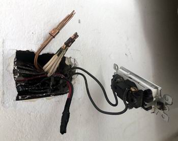
Electrical Question: I am trying to connect a smart light switch. The existing switch only has two black wires connected to it, which I assume are the line and load wire.
How to Wire Light Switch
- I am trying to connect a TP-Llink smart light switch. The existing switch only has two black wires connected to it, which I assume are the line and load wire. the new switch has 4 wires, which all need to be connected – line, load, neutral and ground. Pretty straight forward, or so I thought.
- I pulled all of the wires out of the switch box to locate the neutral and ground wires and found a bundle of ground wires and another bundle of neutral wires clamped together (please see photo). In my limited experience, I have never seen this before. Would I be able to separate one ground and one neutral wire and connect them to the switch?
Thank you!
This electrical wiring question came from Jeff in Honolulu, Hawaii.
Dave’s Reply:
Thanks for your electrical wiring question Jeff.
How to Wire a Smart Light Switch
Application: How to Wire a Smart Light Switch.
Skill Level: Intermediate to Advanced – Best performed by a Licensed Electrical Contractor, or Certified Electrician.
Electrical Tools Required: Basic Electricians Pouch Hand Tools, Voltage Tester, and appropriate Safety Gear.
Estimated Time: Depends on the personal level experience, ability to work with tools, install electrical circuit wiring, and the available access to the project area.
Electrical Safety: Identify the electrical power source to the Light Switch, turn it OFF and Tag with a Note before working with the electrical wiring.
Electrical Wiring Parts and Materials: Electrical parts and materials for the Light Switch should be approved for the specific project and compliant with local and national electrical codes.
Electrical Codes and Inspections: Installing or changing home electrical wiring should be done according to local and national electrical codes as adopted in your specific area of Hawaii. A permit and inspections may also be required.
Wire a TP-Link Smart Light Switch in a Garage
This electrical wiring project is about wiring a smart light switch in the garage of a old house.
Light Switch How to Wire
- From what you have described, and looking at the photo, the home wiring has been installed and crimp connectors have been used for the spliced connections, and this is typical for many older homes.
- Here’s what I typically do in a situation like this: Turn off the circuit power. An additional wire may be added to the group of ground wires as they are now, just trim the ends of the wires evenly and add one more wire, then twist the group together and install a twist on wire connector.
- The group of neutrals will either have to have the crimp connector removed, or the group of wires may be cut just below the crimp, then strip back the insulation, add an additional white wire, twist together, and install a twist on connector. This will provide you with all the wires you need, including the switch wires, to wire up the TP-Link Smart Switch
More about How to Wire a Light Switch
How to Wire a Switch

Wiring a Light Switch – Diagram 1
Wiring Diagrams
Fully Explained Light Switch Wiring Diagrams. Detailed Electrical Wiring Diagrams and Pictures assist your Home Electrical Projects.
Guide to Home Electrical Wire
Electrical Wire for the Home
Complete listing of electrical wire types and parts used for home projects with electrical code information serves as selection guidelines.
Home Electrical Sub-Panels

Sub-Panel Electrical Wiring for the Home
Electrical sub-panel wiring considerations for the home complete with pictures. Careful planning for your Sub-Panel with immediate and future load considerations will help you understand how to size your Sub-Panel. This information will help as you consider a Sub-Panel and its size.
Electrical Boxes for Electric Repairs and Home Wiring Projects

Electrical Junction Boxes for Home Wiring
Understanding electrical junction boxes and what they are used for. Home electrical wiring is the process of installing electrical wire to a location that will serve electrical devices or an appliance. One very important component is the box where the wire will be installed. The type and size of the home wiring electrical boxes will depend upon the circuit size, application and its location.
How to Install Garage Electrical Wiring

Garage Electrical Wiring
Fully Explained Photos and Wiring Diagrams for Garage Electrical Wiring with Code Requirements for most new or remodel projects.
Electrical Grounding and Ground Wires

Electrical Grounding Methods and Requirements
Listing of electrical codes for grounding with examples of electrical grounding codes for home electrical wiring.
Wiring a Smart Light Switch
Electrical Question: I am trying to connect a smart light switch. The existing switch only has two black wires connected to it, which I assume are the line and load wire.
How to Wire Light Switch
- I am trying to connect a TP-Llink smart light switch. The existing switch only has two black wires connected to it, which I assume are the line and load wire. the new switch has 4 wires, which all need to be connected – line, load, neutral and ground. Pretty straight forward, or so I thought.
- I pulled all of the wires out of the switch box to locate the neutral and ground wires and found a bundle of ground wires and another bundle of neutral wires clamped together (please see photo). In my limited experience, I have never seen this before. Would I be able to separate one ground and one neutral wire and connect them to the switch?
Thank you!
This electrical wiring question came from Jeff in Honolulu, Hawaii.
Dave’s Reply:
Thanks for your electrical wiring question Jeff.
How to Wire a Smart Light Switch
Application: How to Wire a Smart Light Switch.
Skill Level: Intermediate to Advanced – Best performed by a Licensed Electrical Contractor, or Certified Electrician.
Electrical Tools Required: Basic Electricians Pouch Hand Tools, Voltage Tester, and appropriate Safety Gear.
Estimated Time: Depends on the personal level experience, ability to work with tools, install electrical circuit wiring, and the available access to the project area.
Electrical Safety: Identify the electrical power source to the Light Switch, turn it OFF and Tag with a Note before working with the electrical wiring.
Electrical Wiring Parts and Materials: Electrical parts and materials for the Light Switch should be approved for the specific project and compliant with local and national electrical codes.
Electrical Codes and Inspections: Installing or changing home electrical wiring should be done according to local and national electrical codes as adopted in your specific area of Hawaii. A permit and inspections may also be required.
Wire a TP-Link Smart Light Switch in a Garage
This electrical wiring project is about wiring a smart light switch in the garage of a old house.
Light Switch How to Wire
- From what you have described, and looking at the photo, the home wiring has been installed and crimp connectors have been used for the spliced connections, and this is typical for many older homes.
- Here’s what I typically do in a situation like this: Turn off the circuit power. An additional wire may be added to the group of ground wires as they are now, just trim the ends of the wires evenly and add one more wire, then twist the group together and install a twist on wire connector.
- The group of neutrals will either have to have the crimp connector removed, or the group of wires may be cut just below the crimp, then strip back the insulation, add an additional white wire, twist together, and install a twist on connector. This will provide you with all the wires you need, including the switch wires, to wire up the TP-Link Smart Switch
More about How to Wire a Light Switch
How to Wire a Switch
Wiring a Light Switch – Diagram 1
Wiring Diagrams
Fully Explained Light Switch Wiring Diagrams. Detailed Electrical Wiring Diagrams and Pictures assist your Home Electrical Projects.
Guide to Home Electrical Wire
Electrical Wire for the Home
Complete listing of electrical wire types and parts used for home projects with electrical code information serves as selection guidelines.
Home Electrical Sub-Panels
Sub-Panel Electrical Wiring for the Home
Electrical sub-panel wiring considerations for the home complete with pictures. Careful planning for your Sub-Panel with immediate and future load considerations will help you understand how to size your Sub-Panel. This information will help as you consider a Sub-Panel and its size.
Electrical Boxes for Electric Repairs and Home Wiring Projects
Electrical Junction Boxes for Home Wiring
Understanding electrical junction boxes and what they are used for. Home electrical wiring is the process of installing electrical wire to a location that will serve electrical devices or an appliance. One very important component is the box where the wire will be installed. The type and size of the home wiring electrical boxes will depend upon the circuit size, application and its location.
How to Install Garage Electrical Wiring
Garage Electrical Wiring
Fully Explained Photos and Wiring Diagrams for Garage Electrical Wiring with Code Requirements for most new or remodel projects.
Electrical Grounding and Ground Wires
Electrical Grounding Methods and Requirements
Listing of electrical codes for grounding with examples of electrical grounding codes for home electrical wiring.
Wiring a Air Compressor with GFCI Protection
Electrical Question: I am installing a 8o gal air compressor that requires a 30 amp circuit breaker, Can I use a 50 amp hot tub GFCI breaker outside as a hook up?
Wiring a GFCI Circuit for a 240Volt Air Compressor
Craig asks: Installing 8o gal air compressor that requires a 30 amp breaker, I have a hot tub hook up that I don’t use anymore with a 50 amp GFCI box located outside and runs to the main breakers box. I have a 30 amp breaker I was planning on using in the main box.
My question is can I use the 50 amp GFCI breaker outside as a hook up or does it need to be the same size breaker as inside the main box? Or should I get another breaker that’s not GFCI and use it as a shut off? Wire is 6 gauge also.
Dave’s Reply:
Thanks for your electrical wiring question Craig.
240Volt Air Compressor with GFCI Protection
Application: Change the Wiring from a Hot Tub to a Air Compressor with GFCI Protection.
Skill Level: Intermediate to Advanced – Best performed by a Licensed Electrical Contractor, or Certified Electrician.
Electrical Tools Required: Basic Electricians Pouch Hand Tools, Voltage Tester, and appropriate Safety Gear.
Estimated Time: Depends on the personal level experience, ability to work with tools, install electrical circuit wiring, and the available access to the project area.
Electrical Safety: Identify the electrical power source to the GFCI Outlet, turn it OFF and Tag with a Note before working with the electrical wiring.
Electrical Wiring Parts and Materials: Electrical parts and materials for the GFCI Outlet should be approved for the specific project and compliant with local and national electrical codes.
Electrical Codes and Inspections: Installing or changing home electrical wiring should be done according to local and national electrical codes as adopted in your specific area of Washington. A permit and inspections may also be required.
Wiring a Air Compressor in a Back Yard
This electrical wiring project is about Changing the Wiring from a Hot Tub GFCI to a GFCI for an Air Compressor in the Back Yard of a Old Home.
Air Compressor Disconnect and GFCI Protection

- Craig, from what you have described, the circuit breaker nearest the air compressor should be a 30amp breaker as it will be serving an air compressor that requires 30amps.
- The 50amp breaker at the main panel for the old hot tub panel can remain as a 50amp but it should be relabeled for the Air Compressor.
- This panel and the air compressor is located outdoor, therefore it requires ground fault protection, therefore it would be best if the breaker in the main panel is a GFCI which will provide ground fault protection for the whole circuit.
- Anytime we are providing power to a device or equipment that is located outdoors, or an electrical cord from the equipment that is leading outdoors then it must have GFCI protection.
- It would be best to place the air compressor in a covered or sheltered enclosure to protect it from the outdoor elements.
See More about How to Change the Wiring a GFCI Outlet
Guide to Home Electrical Wire
Electrical Wire for the Home
Complete listing of electrical wire types and parts used for home projects with electrical code information serves as selection guidelines.
Home Electrical Circuit Breakers
Home Electrical Circuit Breakers
A guide to home electrical circuit breakers and how they work to protect your electrical wiring. When properly installed, your home electrical wiring is protected by a circuit protection device.
How to Wire Electric Outlets

Wiring Electrical Outlets for the Home
Home electrical wiring includes 110 volt outlets and 220 volt outlets and receptacles which are common place in every home. See how wiring electrical outlets for the home are done.
How to Wire GFI Outlets
GFCI and GFI Wiring Diagrams
The features and benefits of GFCI outlets and receptacles will give you a clear understanding of the importance why these safety devices are required by code to help protect you and your family against accidental electrical shock hazards.

GFCI Wiring
This list of articles will help you learn about the features and benefits provided by GFI and GFCI Receptacles and how they are wired.
Home Electrical Wiring Projects

Home Wiring Projects
Installing electrical wiring projects for safety and home improvements.
Wiring a Air Compressor with GFCI Protection
Electrical Question: I am installing a 8o gal air compressor that requires a 30 amp circuit breaker, Can I use a 50 amp hot tub GFCI breaker outside as a hook up?
Wiring a GFCI Circuit for a 240Volt Air Compressor
Craig asks: Installing 8o gal air compressor that requires a 30 amp breaker, I have a hot tub hook up that I don’t use anymore with a 50 amp GFCI box located outside and runs to the main breakers box. I have a 30 amp breaker I was planning on using in the main box.
My question is can I use the 50 amp GFCI breaker outside as a hook up or does it need to be the same size breaker as inside the main box? Or should I get another breaker that’s not GFCI and use it as a shut off? Wire is 6 gauge also.
Dave’s Reply:
Thanks for your electrical wiring question Craig.
240Volt Air Compressor with GFCI Protection
Application: Change the Wiring from a Hot Tub to a Air Compressor with GFCI Protection.
Skill Level: Intermediate to Advanced – Best performed by a Licensed Electrical Contractor, or Certified Electrician.
Electrical Tools Required: Basic Electricians Pouch Hand Tools, Voltage Tester, and appropriate Safety Gear.
Estimated Time: Depends on the personal level experience, ability to work with tools, install electrical circuit wiring, and the available access to the project area.
Electrical Safety: Identify the electrical power source to the GFCI Outlet, turn it OFF and Tag with a Note before working with the electrical wiring.
Electrical Wiring Parts and Materials: Electrical parts and materials for the GFCI Outlet should be approved for the specific project and compliant with local and national electrical codes.
Electrical Codes and Inspections: Installing or changing home electrical wiring should be done according to local and national electrical codes as adopted in your specific area of Washington. A permit and inspections may also be required.
Wiring a Air Compressor in a Back Yard
This electrical wiring project is about Changing the Wiring from a Hot Tub GFCI to a GFCI for an Air Compressor in the Back Yard of a Old Home.
Air Compressor Disconnect and GFCI Protection
- Craig, from what you have described, the circuit breaker nearest the air compressor should be a 30amp breaker as it will be serving an air compressor that requires 30amps.
- The 50amp breaker at the main panel for the old hot tub panel can remain as a 50amp but it should be relabeled for the Air Compressor.
- This panel and the air compressor is located outdoor, therefore it requires ground fault protection, therefore it would be best if the breaker in the main panel is a GFCI which will provide ground fault protection for the whole circuit.
- Anytime we are providing power to a device or equipment that is located outdoors, or an electrical cord from the equipment that is leading outdoors then it must have GFCI protection.
- It would be best to place the air compressor in a covered or sheltered enclosure to protect it from the outdoor elements.
See More about How to Change the Wiring a GFCI Outlet
Guide to Home Electrical Wire
Electrical Wire for the Home
Complete listing of electrical wire types and parts used for home projects with electrical code information serves as selection guidelines.
Home Electrical Circuit Breakers
Home Electrical Circuit Breakers
A guide to home electrical circuit breakers and how they work to protect your electrical wiring. When properly installed, your home electrical wiring is protected by a circuit protection device.
How to Wire Electric Outlets
Wiring Electrical Outlets for the Home
Home electrical wiring includes 110 volt outlets and 220 volt outlets and receptacles which are common place in every home. See how wiring electrical outlets for the home are done.
How to Wire GFI Outlets
GFCI and GFI Wiring Diagrams
The features and benefits of GFCI outlets and receptacles will give you a clear understanding of the importance why these safety devices are required by code to help protect you and your family against accidental electrical shock hazards.
GFCI Wiring
This list of articles will help you learn about the features and benefits provided by GFI and GFCI Receptacles and how they are wired.
Home Electrical Wiring Projects
Home Wiring Projects
Installing electrical wiring projects for safety and home improvements.
Wiring a Under Cabinet LED Light
Electrical Question: I am trying to install new led under cabinet lights, all the wires are are 14 gauge.
How to Wire Under Cabinet Light
Mike asks:
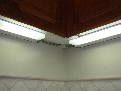
I am trying to install new LED under cabinet lights.
On the first light closest to the switch, there are 2 black, 2 white, and 2 ground wires; all are 14 gauge.
The new LED under cab light can only accept one 14 gauge wire; I cannot shove both black wires (for example) into the slot.
How can I combine 2 wires into one, so that I can insert one wire into the appropriate slot?
This electrical wiring question came from Mike in Los Angeles, California.
Dave’s Reply:
Thanks for your electrical wiring question Mike.
How to Wire a Under Cabinet Light
Application: How to Wire a Under Cabinet Light.
Skill Level: Intermediate to Advanced – Best performed by a Licensed Electrical Contractor, or Certified Electrician.
Electrical Tools Required: Basic Electricians Pouch Hand Tools, Voltage Tester, and appropriate Safety Gear.
Estimated Time: Depends on the personal level experience, ability to work with tools, install electrical circuit wiring, and the available access to the project area.
Electrical Safety: Identify the electrical power source to the Under Cabinet Light, turn it OFF and Tag with a Note before working with the electrical wiring.
Electrical Wiring Parts and Materials: Electrical parts and materials for the Under Cabinet Light should be approved for the specific project and compliant with local and national electrical codes.
Electrical Codes and Inspections: Installing or changing home electrical wiring should be done according to local and national electrical codes as adopted in your specific area of California. A permit and inspections may also be required.
How to Wire a Under Cabinet Light in a Kitchen
This electrical wiring project is about How to Wire a Under Cabinet Light in the Kitchen of a Old Home.

Under Cabinet Light How to Wire
- Mike, from the information you have provided, Yes – this one looks pretty tight.
I would try not twisting the wires, and keep them straight and side by side.
- Or – Install one single wire into the connector, and then splice the single wire with the other two wires outside of the connector.
More about How to Wire a Under Cabinet Light
How to Wire a Switch
Wiring a Light Switch – Diagram 1
Wiring Diagrams
Fully Explained Light Switch Wiring Diagrams. Detailed Electrical Wiring Diagrams and Pictures assist your Home Electrical Projects.
Guide to Home Electrical Wire
Electrical Wire for the Home
Complete listing of electrical wire types and parts used for home projects with electrical code information serves as selection guidelines.
How to Install Kitchen Electrical Wiring

Kitchen Electrical Wiring
Fully Explained Photos and Wiring Diagrams for Kitchen Electrical Wiring with Code Requirements for most new or remodel projects.
Lighting for the Home
Lighting Electrical Codes
How to Install Cabinet Lighting
Installing Under Cabinet Lights
Installing under cabinet lights for your home electrical improvements. This article explains installing under cabinet lights and the lighting features you should know about.
Electrical Grounding
Electrical Grounding Methods and Requirements
Listing of electrical codes for grounding with examples of electrical grounding codes for home electrical wiring.
Wiring a Under Cabinet LED Light
Electrical Question: I am trying to install new led under cabinet lights, all the wires are are 14 gauge.
How to Wire Under Cabinet Light
Mike asks:
I am trying to install new LED under cabinet lights.
On the first light closest to the switch, there are 2 black, 2 white, and 2 ground wires; all are 14 gauge.
The new LED under cab light can only accept one 14 gauge wire; I cannot shove both black wires (for example) into the slot.
How can I combine 2 wires into one, so that I can insert one wire into the appropriate slot?
This electrical wiring question came from Mike in Los Angeles, California.
Dave’s Reply:
Thanks for your electrical wiring question Mike.
How to Wire a Under Cabinet Light
Application: How to Wire a Under Cabinet Light.
Skill Level: Intermediate to Advanced – Best performed by a Licensed Electrical Contractor, or Certified Electrician.
Electrical Tools Required: Basic Electricians Pouch Hand Tools, Voltage Tester, and appropriate Safety Gear.
Estimated Time: Depends on the personal level experience, ability to work with tools, install electrical circuit wiring, and the available access to the project area.
Electrical Safety: Identify the electrical power source to the Under Cabinet Light, turn it OFF and Tag with a Note before working with the electrical wiring.
Electrical Wiring Parts and Materials: Electrical parts and materials for the Under Cabinet Light should be approved for the specific project and compliant with local and national electrical codes.
Electrical Codes and Inspections: Installing or changing home electrical wiring should be done according to local and national electrical codes as adopted in your specific area of California. A permit and inspections may also be required.
How to Wire a Under Cabinet Light in a Kitchen
This electrical wiring project is about How to Wire a Under Cabinet Light in the Kitchen of a Old Home.
Under Cabinet Light How to Wire
- Mike, from the information you have provided, Yes – this one looks pretty tight.
I would try not twisting the wires, and keep them straight and side by side.
- Or – Install one single wire into the connector, and then splice the single wire with the other two wires outside of the connector.
More about How to Wire a Under Cabinet Light
How to Wire a Switch
Wiring a Light Switch – Diagram 1
Wiring Diagrams
Fully Explained Light Switch Wiring Diagrams. Detailed Electrical Wiring Diagrams and Pictures assist your Home Electrical Projects.
Guide to Home Electrical Wire
Electrical Wire for the Home
Complete listing of electrical wire types and parts used for home projects with electrical code information serves as selection guidelines.
How to Install Kitchen Electrical Wiring
Kitchen Electrical Wiring
Fully Explained Photos and Wiring Diagrams for Kitchen Electrical Wiring with Code Requirements for most new or remodel projects.
Lighting for the Home
Lighting Electrical Codes
How to Install Cabinet Lighting
Installing Under Cabinet Lights
Installing under cabinet lights for your home electrical improvements. This article explains installing under cabinet lights and the lighting features you should know about.
Electrical Grounding
Electrical Grounding Methods and Requirements
Listing of electrical codes for grounding with examples of electrical grounding codes for home electrical wiring.
15amp Circuit Breaker Problem
Electrical Question: When I have the lights on and use anything it pops the breaker. Can I change the 15amp to a 20amp breaker?
Tripping Breaker Main Panel
Charles asks:
I have a big garage. The entire garage is on the same 15 amp circuit. When I have the lights on and use anything else it pops the breaker. For example air compressor, 120v welder, or fans (not all at the same time). I was wondering if I can replace the 15 amp for a 20amp breaker. House was built in 2018.
This electrical wiring question came from Charles in Surprise, Arizona.
Dave’s Reply:
Thanks for your electrical wiring question Charles.
Tripping 15amp Breaker Problem
Application: Tripping Breaker a Main Panel.
Skill Level: Intermediate to Advanced – Best performed by a Licensed Electrical Contractor, or Certified Electrician.
Electrical Tools Required: Basic Electricians Pouch Hand Tools, Voltage Tester, and appropriate Safety Gear.
Estimated Time: Depends on the personal level experience, ability to work with tools, install electrical circuit wiring, and the available access to the project area.
Electrical Safety: Identify the electrical power source to the Main Panel, turn it OFF and Tag with a Note before working with the electrical wiring.
Electrical Wiring Parts and Materials: Electrical parts and materials for the Main Panel should be approved for the specific project and compliant with local and national electrical codes.
Electrical Codes and Inspections: Installing or changing home electrical wiring should be done according to local and national electrical codes as adopted in your specific area of Arizona. A permit and inspections may also be required.
Tripping Breaker a Main Panel in a Attached Garage
This electrical wiring project is about Tripping Breaker a Main Panel in the Attached Garage of a New Home.
Overloaded Circuit Causes a 15amp Breaker to Trip Off
- Charles, from the information you have provided, No – the 15amp circuit cannot be replaced with a 20amp circuit breaker because this would cause the electrical wiring to overheat which could create a potential fire hazard.
- It would be best to have an additional electrical circuit installed in the garage.
See More about Tripping Breaker a Main Panel
Home Electrical Codes for Main Service Panels
Electrical Wiring Codes
Home Electrical Sub-Panels
Sub-Panel Electrical Wiring for the Home
Electrical sub-panel wiring considerations for the home complete with pictures. Careful planning for your Sub-Panel with immediate and future load considerations will help you understand how to size your Sub-Panel. This information will help as you consider a Sub-Panel and its size.
Home Electrical Circuit Breakers
Home Electrical Circuit Breakers
A guide to home electrical circuit breakers and how they work to protect your electrical wiring. When properly installed, your home electrical wiring is protected by a circuit protection device.
How to Install Garage Electrical Wiring
Garage Electrical Wiring
Fully Explained Photos and Wiring Diagrams for Garage Electrical Wiring with Code Requirements for most new or remodel projects.
How to Install Workshop Electrical Wiring

Work Shop Electrical Wiring
Fully Explained Photos and Wiring Diagrams for Workshop Electrical Wiring with Code Requirements for most new or remodel projects.
15amp Circuit Breaker Problem
Electrical Question: When I have the lights on and use anything it pops the breaker. Can I change the 15amp to a 20amp breaker?
Tripping Breaker Main Panel
Charles asks:
I have a big garage. The entire garage is on the same 15 amp circuit. When I have the lights on and use anything else it pops the breaker. For example air compressor, 120v welder, or fans (not all at the same time). I was wondering if I can replace the 15 amp for a 20amp breaker. House was built in 2018.
This electrical wiring question came from Charles in Surprise, Arizona.
Dave’s Reply:
Thanks for your electrical wiring question Charles.
Tripping 15amp Breaker Problem
Application: Tripping Breaker a Main Panel.
Skill Level: Intermediate to Advanced – Best performed by a Licensed Electrical Contractor, or Certified Electrician.
Electrical Tools Required: Basic Electricians Pouch Hand Tools, Voltage Tester, and appropriate Safety Gear.
Estimated Time: Depends on the personal level experience, ability to work with tools, install electrical circuit wiring, and the available access to the project area.
Electrical Safety: Identify the electrical power source to the Main Panel, turn it OFF and Tag with a Note before working with the electrical wiring.
Electrical Wiring Parts and Materials: Electrical parts and materials for the Main Panel should be approved for the specific project and compliant with local and national electrical codes.
Electrical Codes and Inspections: Installing or changing home electrical wiring should be done according to local and national electrical codes as adopted in your specific area of Arizona. A permit and inspections may also be required.
Tripping Breaker a Main Panel in a Attached Garage
This electrical wiring project is about Tripping Breaker a Main Panel in the Attached Garage of a New Home.
Overloaded Circuit Causes a 15amp Breaker to Trip Off
- Charles, from the information you have provided, No – the 15amp circuit cannot be replaced with a 20amp circuit breaker because this would cause the electrical wiring to overheat which could create a potential fire hazard.
- It would be best to have an additional electrical circuit installed in the garage.
See More about Tripping Breaker a Main Panel
Home Electrical Codes for Main Service Panels
Electrical Wiring Codes
Home Electrical Sub-Panels
Sub-Panel Electrical Wiring for the Home
Electrical sub-panel wiring considerations for the home complete with pictures. Careful planning for your Sub-Panel with immediate and future load considerations will help you understand how to size your Sub-Panel. This information will help as you consider a Sub-Panel and its size.
Home Electrical Circuit Breakers
Home Electrical Circuit Breakers
A guide to home electrical circuit breakers and how they work to protect your electrical wiring. When properly installed, your home electrical wiring is protected by a circuit protection device.
How to Install Garage Electrical Wiring
Garage Electrical Wiring
Fully Explained Photos and Wiring Diagrams for Garage Electrical Wiring with Code Requirements for most new or remodel projects.
How to Install Workshop Electrical Wiring
Work Shop Electrical Wiring
Fully Explained Photos and Wiring Diagrams for Workshop Electrical Wiring with Code Requirements for most new or remodel projects.
Problem With Electrical Circuits During Hot Weather
Electrical Question: What is causing a problem with my electrical power in my home?
Jay, a Homeowner from San Diego, California asks:
- I have been having a problem when I run the vacuum and plug it in on the west side of my condo, the west side power goes out but then comes back on (by itself) after 5-10 seconds (which I never heard of). I worked around this by plugging it in on the east side of the condo since the cord reaches, problem solved.
- Well, now with the heat, I have been using my portable A/C and experienced the same thing. I cannot use an extension cord for that plus it must be near the door so I can use the exhaust portal.
- Now today I came home from work, did not leave anything on except the fridge, oven/stove and microwave, also the TV & DVR were plugged in but turned off. When I got home, everything was off, then a few seconds and it would try to come back on and turn off again like the circuit breaker was auto-resetting. I went in the guest bedroom and there was no noise at the circuit breaker panel when the East side would come off and immediately turn off. I unplugged every single thing including the fridge, microwave, oven & all lamps, no power at all being used on the east side including nightlights. I turned on the stove and same thing, I was hoping that was my problem.
- I unplugged the stove and plugged in the microwave above it, worked fine. I unplugged the microwave and plugged in the fridge, power went out. I unplugged the fridge and turned on the surge protector for the TV/DVD and power went out. And again, the items would shut down then restart after 10 seconds then shut down almost immediately then restart.
- Any ideas? This is a multi-unit condo, I am on the 3rd floor. I have never lived anywhere where the power will go out then come back on.
Additional Comments: Great website!
Dave’s Reply:
Thanks for your electrical question Jay.
Home Electrical Circuit Problems
Application: Electric Power Problem.
Skill Level: Advanced – Best performed by a Licensed Electrical Contractor and may require the local utility company or electric service provider.
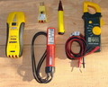
Tools Required: Basic Electricians Pouch Hand Tools, Voltage Tester or Multimeter.
Estimated Time: Depends on personal level experience, ability to work with tools and troubleshoot and inspect electrical circuits and electrical system components.
Precaution: Depending on the symptoms, identify the main panel or panel circuit in question, turn it OFF and Tag it with a Note before working with the wiring.
Notice: Burnt or damaged electrical wiring and circuit components should be replaced with new electrical materials of the same voltage and amperage rating.
Guide to Troubleshooting Electric Circuit Problems
- Jay this sounds like a connection problem at the electrical panel with one of the main incoming electrical lines, most likely the neutral wire, or it could be a main circuit breaker that has a deteriorating connection with an internal panel component.
- This is a very common electrical problem that occurs when the outside temperatures rise which will cause the electrical loads (air conditioning, etc.) to increase, thereby causing expansion and contraction of the electrical components, especially those components which are aluminum type materials and or aluminum wire.
- This electrical problem will require testing and troubleshooting starting at the electrical panel that feeds your home electrical circuits. This is a problem that requires an experienced qualified licensed electrician.
More about Troubleshooting Home Electrical Problems
Using Electrical Testers and Meters
Understanding Electrical Testers
When working on home electrical wiring using voltage testers can play an important part in electrical safety. Electrical testers enable you to identify electrical circuits and help prevent the possibility of accidental electrical shock.
How to Repair Electric Wiring

How to Troubleshoot and Repair Electrical Wiring
Licensed Electrician Reveals the Secrets of Successful Electrical Troubleshooting Methods used to solve the majority of the home electrical problems and wiring failures encountered.
Basic Home Wiring Circuits

House Wiring Circuits and Circuit Breakers
This article looks at common 120 volt and 240 volt house wiring circuits and the circuit breakers that are installed identifying the types and amperage sizes used in most homes.
Electric Circuit Breakers
Electrical Circuit Breakers
A guide to home electrical circuit breakers and how they work to protect your electrical wiring. When properly installed, your home electrical wiring is protected by a circuit protection device.
Problem With Electrical Circuits During Hot Weather
Electrical Question: What is causing a problem with my electrical power in my home?
Jay, a Homeowner from San Diego, California asks:
- I have been having a problem when I run the vacuum and plug it in on the west side of my condo, the west side power goes out but then comes back on (by itself) after 5-10 seconds (which I never heard of). I worked around this by plugging it in on the east side of the condo since the cord reaches, problem solved.
- Well, now with the heat, I have been using my portable A/C and experienced the same thing. I cannot use an extension cord for that plus it must be near the door so I can use the exhaust portal.
- Now today I came home from work, did not leave anything on except the fridge, oven/stove and microwave, also the TV & DVR were plugged in but turned off. When I got home, everything was off, then a few seconds and it would try to come back on and turn off again like the circuit breaker was auto-resetting. I went in the guest bedroom and there was no noise at the circuit breaker panel when the East side would come off and immediately turn off. I unplugged every single thing including the fridge, microwave, oven & all lamps, no power at all being used on the east side including nightlights. I turned on the stove and same thing, I was hoping that was my problem.
- I unplugged the stove and plugged in the microwave above it, worked fine. I unplugged the microwave and plugged in the fridge, power went out. I unplugged the fridge and turned on the surge protector for the TV/DVD and power went out. And again, the items would shut down then restart after 10 seconds then shut down almost immediately then restart.
- Any ideas? This is a multi-unit condo, I am on the 3rd floor. I have never lived anywhere where the power will go out then come back on.
Additional Comments: Great website!
Dave’s Reply:
Thanks for your electrical question Jay.
Home Electrical Circuit Problems
Application: Electric Power Problem.
Skill Level: Advanced – Best performed by a Licensed Electrical Contractor and may require the local utility company or electric service provider.
Tools Required: Basic Electricians Pouch Hand Tools, Voltage Tester or Multimeter.
Estimated Time: Depends on personal level experience, ability to work with tools and troubleshoot and inspect electrical circuits and electrical system components.
Precaution: Depending on the symptoms, identify the main panel or panel circuit in question, turn it OFF and Tag it with a Note before working with the wiring.
Notice: Burnt or damaged electrical wiring and circuit components should be replaced with new electrical materials of the same voltage and amperage rating.
Guide to Troubleshooting Electric Circuit Problems
- Jay this sounds like a connection problem at the electrical panel with one of the main incoming electrical lines, most likely the neutral wire, or it could be a main circuit breaker that has a deteriorating connection with an internal panel component.
- This is a very common electrical problem that occurs when the outside temperatures rise which will cause the electrical loads (air conditioning, etc.) to increase, thereby causing expansion and contraction of the electrical components, especially those components which are aluminum type materials and or aluminum wire.
- This electrical problem will require testing and troubleshooting starting at the electrical panel that feeds your home electrical circuits. This is a problem that requires an experienced qualified licensed electrician.
More about Troubleshooting Home Electrical Problems
Using Electrical Testers and Meters
Understanding Electrical Testers
When working on home electrical wiring using voltage testers can play an important part in electrical safety. Electrical testers enable you to identify electrical circuits and help prevent the possibility of accidental electrical shock.
How to Repair Electric Wiring
How to Troubleshoot and Repair Electrical Wiring
Licensed Electrician Reveals the Secrets of Successful Electrical Troubleshooting Methods used to solve the majority of the home electrical problems and wiring failures encountered.
Basic Home Wiring Circuits
House Wiring Circuits and Circuit Breakers
This article looks at common 120 volt and 240 volt house wiring circuits and the circuit breakers that are installed identifying the types and amperage sizes used in most homes.
Electric Circuit Breakers
Electrical Circuit Breakers
A guide to home electrical circuit breakers and how they work to protect your electrical wiring. When properly installed, your home electrical wiring is protected by a circuit protection device.
More about:
How do I identify home electrical problems?
Wire a Dryer with a 3 Prong Cord or 4 Prong Cord
Smart Light Switch Wire Connections
Wiring an Air Compressor that is Outside
Wiring a New LED Under Cabinet Light
Can I Replace a 15amp for a 20amp Breaker?
Why Summer Heat May Cause Problems with Electrical Circuits
Installing Ceiling Fan Wiring
|