Connecting a Single Phase Motor to a Contactor

|
How do I connect a single phase contactor to power an electric motor?
© By: Dave Rongey
|
How Contactors are Wired to Control Single Phase Motors
[ad#block]Question: How do I connect a single phase contactor to power an electric motor?
This electrical question came from: Tobi, a Homeowner from Warri, Idaho.
See more about Home Wiring for Idaho
Dave’s Reply:
Thanks for your electrical question Tobi.
Electrical Wiring for Single Phase Motor Controls
Tobi, a motor control is simply a relay contactor that acts as a switch which is activated by a different power source or a control circuit. The control circuit may be operated manually, or automatically when the control circuit is wired through sensors or other control devices. The single phase contactor is sized according to the electric motor voltage and amperage, and the control circuit is designed for the specific type of devices that will be used to control the single phase motor. The control circuit is typically a lower voltage than the motor voltage.
The Following links will assist you with your electrical question:
All About Electrical Control Relays for Motors

Understanding Electrical Relays
The use of relays that are sometimes needed to control special device loads such as Air Conditioners and other high demand equipment from starting at the same time.
You identified your project to be about Electrical Wiring, so you might find this information useful:
Electrical Wiring

Electrical Wiring
Home electrical wiring projects with pictures and wiring diagrams.
The following may also be helpful for you:

A Complete Guide to Home Electrical Wiring
Be sure to get your copy of my BIG Book:
Perfect for Homeowners, Students and Electricians
Includes:
Home Electrical Wiring - Room by Room
120 Volt Circuits
240 Volt Circuits
Multi-Wired Circuits
Wiring Methods for Installing Home Electrical Circuit Wiring
Electrical Codes for Home Electrical Wiring
....and much more.
|
Be Careful and Be Safe - Never Work on Energized Circuits!
Consult your Local Building Department about Permits and Inspections for all Electric Wiring Projects.
Electrical Tips to Help You Wire it Right
|

The Safest Way to Test Electrical Devices and Identify Electric Wires!
The Non-Contact Electrical Tester
This is a testing tool that I have had in my personal electrical tool pouch for years, and is the first test tool I grab to help identify electrical wiring. It is a Non-contact tester that I use to easily Detect Voltage in Cables, Cords, Circuit Breakers, Lighting Fixtures, Switches, Outlets and Wires. Simply insert the end of the tester into an outlet, lamp socket, or hold the end of the tester against the wire you wish to test. Very handy and easy to use.

The Quickest Way to Check for Faulty Electrical Wiring!
The Plug-In Outlet Tester
This is the first tool I grab to troubleshoot a problem with outlet circuit wiring. This popular tester is also used by most inspectors to test for power and check the polarity of circuit wiring.
It detects probable improper wiring conditions in standard 110-125 VAC outlets
Provides 6 probable wiring conditions that are quick and easy to read for ultimate efficiency
Lights indicate if wiring is correct and indicator light chart is included
Tests standard 3-wire outlets
UL Listed
Light indicates if wiring is incorrect
Very handy and easy to use.

Strip Off Wire Insulation without Nicking and Damaging the Electric Wire!
The Wire Stripper and Wire Cutter
My absolute favorite wire stripping tool that I have had in my personal electrical tool pouch for years, and this is the tool I use to safely strip electrical wires.
This handy tool has multiple uses:
The wire gauges are shown on the side of the tool so you know which slot to use for stripping insulation.
The end of the tool can be used to grip and bend wire which is handy for attaching wire onto the screw terminals of switches and outlets..
The wire stripper will work on both solid and stranded wire. This tool is Very Handy and Easy to Use.
|
Electrical Parts to Help You Wire it Right
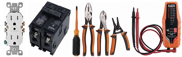
Residential Electrical Parts and Accessories
Light Switches
120volt Outlets
Circuit Breakers
Electrician Tools
Voltage Testers
|
More about: Connectingsingle phase motor tocontactor
|
More articles about Electrical, Motor and Home Electrical Wiring:
|
|
« Previous |
Next » |
|
|
|


