


Replacing Three Way Switches

|
Three way switch wiring diagrams to help when wiring replacement switches. © By: Dave Rongey |
Wiring Connections for Three Way Switches
[ad#block]Question: I have a Sears whole house fan installed about 15 years ago that can be operated from upstairs or downstairs with 2 separate sets of timer and speed control switches, one set upstairs and the other set downstairs. One of the speed control switches failed and I located another. I thought I installed it correctly but now the other (downstairs) control doesn’t work, only the upstairs control that I replaced the rheostat/speed control switch. Can you give me a wiring diagram for this configuration so I can get it working?
Thanks.
This electrical question came from: Mark, from Irvine, California
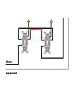
Wiring Diagrams for Three Way Switches
Mark, follow the link below for three way switch wiring diagrams. When three way switches are replaced the traveler wires can be connected to the wrong terminal or attached to the wrong lead of the timer switch. This can be easily corrected once the wires are identified, as you will see on the wiring diagrams.
See more about Home Wiring for California
Dave’s Reply:
Thanks for your electrical question Mark
The Following links will assist you with your electrical question:
Electrical Wiring Diagrams
Home electrical wiring diagrams are an important tool for completing your electrical projects. An electrical wiring diagram can be as simple as a diagram showing how to install a new switch in your hallway, or as complex as the complete electrical blueprint for your new home or home improvement project.
The following may also be helpful for you:
|
|

Be Careful and Be Safe - Never Work on Energized Circuits!
Consult your Local Building Department about Permits and Inspections for all Electric Wiring Projects.
The Safest Way to Test Electrical Devices and Identify Electric Wires!The Non-Contact Electrical TesterThis is a testing tool that I have had in my personal electrical tool pouch for years, and is the first test tool I grab to help identify electrical wiring. It is a Non-contact tester that I use to easily Detect Voltage in Cables, Cords, Circuit Breakers, Lighting Fixtures, Switches, Outlets and Wires. Simply insert the end of the tester into an outlet, lamp socket, or hold the end of the tester against the wire you wish to test. Very handy and easy to use.
The Quickest Way to Check for Faulty Electrical Wiring!The Plug-In Outlet TesterThis is the first tool I grab to troubleshoot a problem with outlet circuit wiring. This popular tester is also used by most inspectors to test for power and check the polarity of circuit wiring. It detects probable improper wiring conditions in standard 110-125 VAC outlets Provides 6 probable wiring conditions that are quick and easy to read for ultimate efficiency Lights indicate if wiring is correct and indicator light chart is included Tests standard 3-wire outlets UL Listed Light indicates if wiring is incorrect Very handy and easy to use.
Strip Off Wire Insulation without Nicking and Damaging the Electric Wire!The Wire Stripper and Wire CutterMy absolute favorite wire stripping tool that I have had in my personal electrical tool pouch for years, and this is the tool I use to safely strip electrical wires. This handy tool has multiple uses: The wire gauges are shown on the side of the tool so you know which slot to use for stripping insulation. The end of the tool can be used to grip and bend wire which is handy for attaching wire onto the screw terminals of switches and outlets.. The wire stripper will work on both solid and stranded wire. This tool is Very Handy and Easy to Use. |
||


More articles about Three Way Switches and Home Electrical Wiring: |
|
| « Previous | Next » |
Fire Alarm System Wiring |
Installing an Exhaust Fan and Light |


