Electrical Tips to Help You Wire it Right
|

The Safest Way to Test Electrical Devices and Identify Electric Wires!
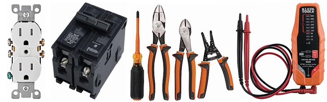
The Non-Contact Electrical Tester
This is a testing tool that I have had in my personal electrical tool pouch for years, and is the first test tool I grab to help identify electrical wiring. It is a Non-contact tester that I use to easily Detect Voltage in Cables, Cords, Circuit Breakers, Lighting Fixtures, Switches, Outlets and Wires. Simply insert the end of the tester into an outlet, lamp socket, or hold the end of the tester against the wire you wish to test. Very handy and easy to use.

The Quickest Way to Check for Faulty Electrical Wiring!
The Plug-In Outlet Tester
This is the first tool I grab to troubleshoot a problem with outlet circuit wiring. This popular tester is also used by most inspectors to test for power and check the polarity of circuit wiring.
It detects probable improper wiring conditions in standard 110-125 VAC outlets
Provides 6 probable wiring conditions that are quick and easy to read for ultimate efficiency
Lights indicate if wiring is correct and indicator light chart is included
Tests standard 3-wire outlets
UL Listed
Light indicates if wiring is incorrect
Very handy and easy to use.

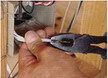
Strip Off Wire Insulation without Nicking and Damaging the Electric Wire!
The Wire Stripper and Wire Cutter
My absolute favorite wire stripping tool that I have had in my personal electrical tool pouch for years, and this is the tool I use to safely strip electrical wires.
This handy tool has multiple uses:
The wire gauges are shown on the side of the tool so you know which slot to use for stripping insulation.
The end of the tool can be used to grip and bend wire which is handy for attaching wire onto the screw terminals of switches and outlets..
The wire stripper will work on both solid and stranded wire. This tool is Very Handy and Easy to Use.
|