» Wiring Electrical Control Relays
» Need Electrical Help? Ask the Electrician
Electrical Relay Construction and Purpose - Part 5

|
By Dave Rongey
Summary: This section will discusses the limitations of solid state relays due to contacts, size and operation speed. © By: Dave Rongey |
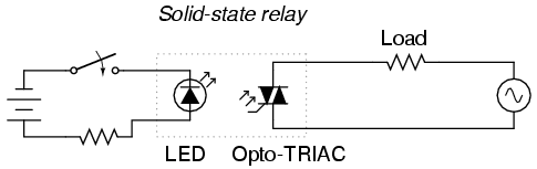
The Basics of using Solid-State Relays
To address these limitations, many relay manufacturers offer "solid-state" relays, which use an SCR, TRIAC, or transistor output instead of mechanical contacts to switch the controlled power.
The output device (SCR, TRIAC, or transistor) is optically-coupled to an LED light source inside the relay.
The relay is turned on by energizing this LED, usually with low-voltage DC power. This optical isolation between input to output rivals the best that electromechanical relays can offer.
|
As versatile as electromechanical relays can be, they do suffer many limitations. They can be expensive to build, have a limited contact cycle life, take up a lot of room, and switch slowly, compared to modern semiconductor devices. These limitations are especially true for large power contactor relays. |
 |
Being solid-state devices, there are no moving parts to wear out, and they are able to switch on and off much faster than any mechanical relay armature can move. There is no sparking between contacts, and no problems with contact corrosion. However, solid-state relays are still too expensive to build in very high current ratings, and so electromechanical contactors continue to dominate that application in industry today. |
|
One significant advantage of a solid-state SCR or TRIAC relay over an electromechanical device is its natural tendency to open the AC circuit only at a point of zero load current. Because SCR's and TRIAC's are thyristors, their inherent hysteresis maintains circuit continuity after the LED is de-energized until the AC current falls below a threshold value (the holding current). In practical terms what this means is the circuit will never be interrupted in the middle of a sine wave peak. Such untimely interruptions in a circuit containing substantial inductance would normally produce large voltage spikes due to the sudden magnetic field collapse around the inductance. This will not happen in a circuit broken by an SCR or TRIAC. This feature is called zero-crossover switching. |
|
One disadvantage of solid state relays is their tendency to fail "shorted" on their outputs, while electromechanical relay contacts tend to fail "open." In either case, it is possible for a relay to fail in the other mode, but these are the most common failures. Because a "fail-open" state is generally considered safer than a "fail-closed" state, electromechanical relays are still favored over their solid-state counterparts in many applications. |