Electrician Training Electrical Certification wiring recessed light fixtures Electrical Wiring Electrical Troubleshooting and Electrical Repairs wire outdoor light fixture Home Electrical Wiring Diagrams

wiring home generator and transfer switch wiring a 220 volt range cord outlet Wiring for GFCI Outlets Wiring Outlets and a Switched Outlet Wiring and Installing Ceiling Fans and Remote Controls wire dimmer switch wiring diagrams for switches wiring a dryer cord and 220 outlet circuit breaker panel
Electrical Wire and Cable
ask the electrician
Electrician Training Electrical Certification wiring recessed light fixtures Electrical Wiring Electrical Troubleshooting and Electrical Repairs wire outdoor light fixture Home Electrical Wiring Diagrams
wiring home generator and transfer switch wiring a 220 volt range cord outlet Wiring for GFCI Outlets Wiring Outlets and a Switched Outlet How to Installing and Wire Ceiling Fans and Remote Controls wire dimmer switch wiring diagrams for switches wiring a dryer cord and 220 outlet circuit breaker panel
Electrical Wire and Cable

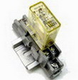
Electrical Relay Construction and Purpose - Part 4

relay-panel
By
Summary: This section explains how protective relays are used to monitor the current, voltage, frequency and more in the electrical power industry.


How and Where Protective Relays Are Used


Electrical Wiring Video

Install a Generator and Transfer Switch Panel

NOTE: A List of All my Helpful Videos

Will Display at the End of This Video

So Keep Watching So I Can Help You Wire it Right!


Check out my YouTube Channel:
» AskTheElectrician «
and Subscribe!


The circuit breakers which are used to switch large quantities of electric power on and off are actually electromechanical relays, themselves. Unlike the circuit breakers found in residential and commercial use which determine when to trip (open) by means of a bimetallic strip inside that bends when it gets too hot from overcurrent, large industrial circuit breakers must be "told" by an external device when to open. Such breakers have two electromagnetic coils inside: one to close the breaker contacts and one to open them.

Protective Relays

A special type of relay is one which monitors the current, voltage, frequency, or any other type of electric power measurement either from a generating source or to a load for the purpose of triggering a circuit breaker to open in the event of an abnormal condition. These relays are referred to in the electrical power industry as protective relays.

The "trip" coil can be energized by one or more protective relays, as well as by hand switches, connected to switch 125 Volt DC power. DC power is used because it allows for a battery bank to supply close/trip power to the breaker control circuits in the event of a complete (AC) power failure.

Protective relays can monitor large AC currents by means of current transformers (CT's), which encircle the current-carrying conductors exiting a large circuit breaker, transformer, generator, or other device. Current transformers step down the monitored current to a secondary (output) range of 0 to 5 amps AC to power the protective relay. The current relay uses this 0-5 amp signal to power its internal mechanism, closing a contact to switch 125 Volt DC power to the breaker's trip coil if the monitored current becomes excessive.

Likewise, (protective) voltage relays can monitor high AC voltages by means of voltage, or potential, transformers (PT's) which step down the monitored voltage to a secondary range of 0 to 120 Volts AC, typically. Like (protective) current relays, this voltage signal powers the internal mechanism of the relay, closing a contact to switch 125 Volt DC power to the breaker's trip coil is the monitored voltage becomes excessive.

There are many types of protective relays, some with highly specialized functions. Not all monitor voltage or current, either. They all, however, share the common feature of outputting a contact closure signal which can be used to switch power to a breaker trip coil, close coil, or operator alarm panel. Most protective relay functions have been categorized into an ANSI standard number code. Here are a few examples from that code list:

ANSI protective relay designation numbers

12 = Over speed
24 = Over excitation
25 = Syncrocheck
27 = Bus/Line under voltage
32 = Reverse power (anti-motoring)
38 = Stator over temp (RTD)
39 = Bearing vibration
40 = Loss of excitation
46 = Negative sequence undercurrent (phase current imbalance)
47 = Negative sequence under voltage (phase voltage imbalance)
49 = Bearing over temp (RTD)
50 = Instantaneous overcurrent
51 = Time overcurrent
51V = Time overcurrent -- voltage restrained
55 = Power factor
59 = Bus over voltage
60FL = Voltage transformer fuse failure
67 = Phase/Ground directional current
79 = Auto recolse
81 = Bus over/under frequency

  • REVIEW:
  • Large electric circuit breakers do not contain within themselves the necessary mechanisms to automatically trip (open) in the event of overcurrent conditions. They must be "told" to trip by external devices.
  • Protective relays are devices built to automatically trigger the actuation coils of large electric circuit breakers under certain conditions.
» You Can Avoid Costly Mistakes! «

Here's How to Do It:
Wire It Right with the help of my Illustrated Wiring Book

Great for any Home Wiring Project.


See How to Wire it Right!

Learn more about Residential House Wiring
Complete Guide to Home Electrical Wiring
Perfect for Homeowners, Students and Electricians
Includes:
Home Electrical Wiring - Upgrade Electrical Wiring
Wiring 120 Volt Circuits
Wiring 240 Volt Circuits
Wiring Multi-Wired Circuits
Wiring Methods for Installing Home Electrical Circuit Wiring
Electrical Codes for Home Electrical Wiring
Electrical Troubleshooting and Repairs
....and much more.

» Click here to learn more about Home Electrical Wiring «
  electrical wiring
Electrical Wiring Book


Electrical Tips to Help You Wire it Right

The Safest Way to Test Electrical Devices and Identify Electric Wires!

The Non-Contact Electrical Tester
This is a testing tool that I have had in my personal electrical tool pouch for years, and is the first test tool I grab to help identify electrical wiring. It is a Non-contact tester that I use to easily Detect Voltage in Cables, Cords, Circuit Breakers, Lighting Fixtures, Switches, Outlets and Wires. Simply insert the end of the tester into an outlet, lamp socket, or hold the end of the tester against the wire you wish to test. Very handy and easy to use.

The Quickest Way to Check for Faulty Electrical Wiring!

The Plug-In Outlet Tester
This is the first tool I grab to troubleshoot a problem with outlet circuit wiring. This popular tester is also used by most inspectors to test for power and check the polarity of circuit wiring.
It detects probable improper wiring conditions in standard 110-125 VAC outlets Provides 6 probable wiring conditions that are quick and easy to read for ultimate efficiency Lights indicate if wiring is correct and indicator light chart is included Tests standard 3-wire outlets UL Listed Light indicates if wiring is incorrect Very handy and easy to use.

Strip Off Wire Insulation without Nicking and Damaging the Electric Wire!

The Wire Stripper and Wire Cutter
My absolute favorite wire stripping tool that I have had in my personal electrical tool pouch for years, and this is the tool I use to safely strip electrical wires.
This handy tool has multiple uses:
The wire gauges are shown on the side of the tool so you know which slot to use for stripping insulation.
The end of the tool can be used to grip and bend wire which is handy for attaching wire onto the screw terminals of switches and outlets..

The wire stripper will work on both solid and stranded wire. This tool is Very Handy and Easy to Use.

electrical parts

Residential Electrical Parts and Accessories


Light Switches

120volt Outlets

Circuit Breakers

Electrician Tools

Voltage Testers


RELATED


More about Electrical Relay Construction and Purpose Part4

Sitemap
Ceiling Fans Airplane Ceiling Fan Airplane Ceiling Fan Ceiling Fan Direction Summer Ceiling Fan Direction Winter Ceiling Fan Wiring Diagram 1 Ceiling Fan Wiring Diagram 2 Ceiling Fan Wiring Questions and Answers Ceiling Fans Wiring – Part 1 Ceiling Fans Wiring – Part 2 Introduction to Ceiling Fan Remote Controls Outdoor Ceiling Fan 1 Outdoor […]W-1975 C-0

Electrical Relay Construction and Purpose Part4 - 373